
Quick Setup Guide


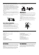
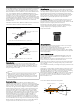

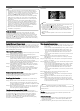
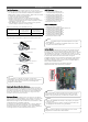

Table Of Contents

7
Wiring
• Ensure the power wiring / communication cable shield (if
shielded) from the outdoor unit to the indoor units / branch
distribution units is properly grounded to the outdoor unit
chassis only. Do not ground at any other point. Wiring must
comply with all applicable local and national codes.
• Use a conduit for the communications / connection (power)
cable from the outdoor unit to the indoor units and branch
distribution unit(s). Electrical interference my cause product
malfunction.
• The communications / connection (power) cable from the
outdoor unit to the indoor units / branch distribution unit(s)
must be separated and isolated from power wiring to the
outdoor unit, computers, radio and television broadcasting
facilities, as well as medical imaging equipment. Electrical
interference my cause product malfunction.
• Pipes and wires should be purchased separately for
installation of the product.
NOTE
!
• The terminals labeled “GND” are NOT ground terminals. The
terminals labeled ARE ground terminals.
• Polarity matters. Always connect “A” to “A” and “B” to “B.”
• Always create a wiring diagram that contains the exact
sequence in which all the indoor units and branch distribution
units (Multi F MAX systems onlyare wired in relation to the
outdoor unit.
• Do not include splices or wire nuts in the communication
cable.
NOTE
!
Wiring Connections
LG uses a “JIS” type of screw for all terminals; use a JIS
screwdriver to tighten and loosen these screws and avoid
damaging the terminal. Use a solderless ring or fork connection
when possible. Do not over tighten the connections — over
tightening may damage the terminals — but firmly and securely
attach the wiring in a way to prevent external forces from being
imparted on the terminal block.
The triple evacuation procedure is a best practices
recommendation for Multi F systems, but mandatory for Multi F
MAX systems.
NOTE
!
JIS Screws.
Final Installation Procedures
Perform Triple Leak / Pressure Check
After the refrigerant piping installation is complete, perform a triple
leak / pressure test to check for leaks at any joints or connections
within the piping system. Perform the Triple / Leak Pressure Check
with only the piping system and indoor units / heat recovery units.
Use medical grade dry nitrogen.
Triple Leak / Pressure Procedure
Step 1: Perform the leak / pressure check at 150 psig for 5 minutes
(standing pressure check).
Step 2: Perform the leak / pressure check at 300 psig for 15
minutes (standing pressure check).
Step 3: Perform the leak / pressure check at 550 psig for 24 hours
to make sure the piping system is leak-free. After the
gauge reading reaches 550 psig, isolate the system by first
closing the gauge manifold, then close the nitrogen
cylinder valve. Check the flared and brazed connections for
leaks by applying a bubble solution to all joints.
Step 4: If the pressure does NOT drop for 24 hours, the system
passes the test. See how ambient conditions may affect
the pressure test below.
Step 5: If the pressure drops and it is not due to ambient
conditions, there is a leak and it must be found. Remove
the bubble solution with a clean cloth, repair the leak(s),
and perform the leak / pressure check again.
Perform Deep Evacuation (Multi F)
On Multi F systems, after the leak / pressure check is complete,
the deep evacuation procedure must be performed to the
refrigerant piping and all connected indoor units.
Deep Evacuation Procedure
Step 1: Evacuate to static micron level ≤500 for at least one (1)
hour.
Step 2: Micron level must remain ≤500 for two (2) hours. If the
vacuum gauge rises and stops, the system may contain
moisture; therefore, it will be necessary to repeat the steps
of vacuum break and drying.
Step 3: After maintaining the system in vacuum for two (2) hours,
check if the vacuum gauge rises or not. If it doesn’t rise,
then the system is properly evacuated.
Triple Evacuation Procedure (Multi F MAX)
On Multi F MAX systems, after the leak / pressure check is
complete, the triple evacuation procedure must be performed to
the refrigerant piping and all connected indoor units / branch
distribution units. Do not just perform the deep evacuation
procedure on Multi F MAX systems. The deep evacuation
procedure is insufficient to fully evacuate the extensive piping
systems on Multi F MAX products.
Triple Evacuation Procedure Steps
Step 1: Operate the vacuum pump and evacuate the system to the
2,000 micron level. Isolate the pump, and then watch the
micron level.
• If the micron level DOES NOT stop rising, there is a leak.
• If the micron level DOES rise above 2,000 micron, re-
open the manifold gauges and the vacuum pump valve
and continue evacuation back down to 2,000 micron
level.
• If the micron level holds at 2,000 micron, continue to the
next step.
Step 2: Break vacuum with 50 psig nitrogen purge for an
appropriate amount of time (this is to “sweep” moisture
from piping).
Step 3: Purge nitrogen from the system until the pressure drops
down to 1 to 3 psig.
Step 4: Evacuate to 1,000 micron level. Isolate the pump and then
watch the micron level.
• If the micron level DOES NOT stop rising, there is a leak.
• If the micron level DOES rise above 1,000 micron, re-
open the manifold gauges and the vacuum pump valve,
and continue evacuation back down to 1,000 micron
level.
• If the micron level holds at 1,000 micron, continue to the
next step.
Step 5: Break vacuum with 50 psig nitrogen purge for an
appropriate amount of time.
Step 6: Purge nitrogen from the system until the pressure drops
down to 1 to 3 psig.
Step 7: Evacuate to static micron level ≤ 500 for at least one (1)
hour.
Step 8: Micron level must remain ≤ 500 for two (2) hours. If the
vacuum gauge rises and stops, the system may contain
moisture; therefore, it will be necessary to repeat the steps
of vacuum break and drying.
Test Run
After the triple leak / pressure and evacuation procedures are
complete, perform a test run.
Before the Test Run
1. Check that all condensate tubing, refrigerant piping and power
wiring, and communication / connection (power) cables are
properly connected.
2. Make sure that the gas and liquid service valves are fully open.