
Quick Setup Guide


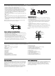
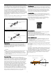

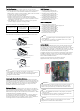

Table Of Contents

6
Piping Supports
A properly installed piping system is adequately supported to avoid
piping sags (sagging pipes become oil traps that lead to equipment
malfunction).
Field-provided piping supports must be designed to meet local
codes. As necessary, place supports closer for segments where
sagging could
potentially occur. Maximum spacing of pipe supports must meet
local codes, but if there are no specifications in the local codes,
then the piping must be supported:
• Minimum of 20 inches recommended between long radius 90
degree elbows, and between the Y-branch and the branch
distribution unit.
• Maximum 5 feet on center for straight segments of pipe up to
3/4 inches outside dia. size.
• Maximum of 6 feet on center for pipe up to 1 inch outside
diameter size.
• Wherever the pipe changes direction, place a hanger within 12
inches on one side and within 12 to 19 inches of the bend on the
other side.
Examples of Piping Supports.
Piping Insulation
ALL piping and piping connections in a Multi F / Multi F MAX
system must be insulated; a minimum 1/2 inch wall, closed cell
with vapor barrier insulation is recommended (follow all local, sate,
and national requirements). Insulate all piping separately. If
improperly insulated, condensate may form on the outside of the
piping and water damage within building may occur, the Multi F /
Multi F MAX system will lose capacity, or heat may move from the
Multi F / Multi F MAX system to the surrounding air.
LATS
Indoor / outdoor unit locations and piping routes MUST be finalized
prior to piping work to determine actual lengths. After piping
installation starts, all changes in proposed lengths must be
forwarded to the designer for re-calculation in LATS and a NEW
Field Drawing produced before pipe is installed.
Max.
12"
12"–19"
Rule for Changes in Piping Direction.
Pay attention to a possible change in unit capacities as piping
lengths change! If piping lengths to be installed are not those
as specified in LATS, a new LATS file MUST be produced
BEFORE pipe work begins!
NOTE
!
Wiring
•
All power wiring and communication cable installation must be
performed by authorized service providers working in accordance
with local, state, and National Wiring Code regulations.
• Install appropriately sized breakers / fuses / overcurrent
protection switches and wiring in accordance with local, state,
and National Wiring Code regulations. Using inappropriately
sized electrical components may result in electric shock,
physical injury, or death.
• Properly ground all outdoor units and indoor units. Do NOT
connect ground wire to refrigerant, gas, or water piping; to
lightening rods; to telephone ground wiring; or to the building
plumbing system. Failure to properly provide an National
Wiring Code approved earth ground can result in electric
shock, physical injury or death.
• Properly terminate all wiring. If wires are not properly
terminated and attached, there is risk of fire, electric shock,
and physical injury or death.
WARNING
!
Power Wiring and Communication / Connection (Power) Cable
Specifications
Multi F / Multi F MAX outdoor units operate at 1Ø, 208-230V,
60Hz, and power is wired to the outdoor unit only. The outdoor unit
supplies power to the indoor units and the branch distribution units
through the communication / connection (power) cable.
Power supply to the outdoor unit must be selected based on
National Wiring Code and local codes. Maximum allowable voltage
fluctuation ±10% or nameplate rated value. Wiring must be solid or
stranded, and must comply with all local and national electrical
codes. Properly ground the outdoor unit per National Wiring Code
and local codes.
Multi F communication / connection (power) cable from the
outdoor unit to the indoor unit must be a minimum of 18 AWG,
four (4) conductor, stranded, shielded or unshielded.
Multi F MAX communication / connection (power) cable from the
outdoor unit to the branch distribution unit(s) must be a minimum
of 16 AWG, four (4) conductor, stranded, shielded or unshielded.
Multi F MAX communication / connection (power) cable from the
branch distribution unit(s) to the indoor units must be a minimum
of 18 AWG, four (4) conductor, stranded, shielded or unshielded.
Y-branch Installation Alignment Specification.
Vertical Up
Configuration
Vertical Down
Configuration
Within ± 3°Within ± 3°