
Quick Setup Guide


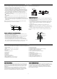
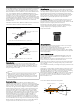

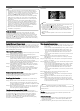
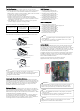

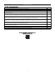
Table Of Contents

5
Piping
Multi F MAX outdoor units have one set (one vapor and one liquid)
of flare-type connections. Field-installed piping links the outdoor
unit connections to a branch distribution unit. If installing two (2)
branch distribution units in parallel on one (1) Multi F MAX outdoor
unit, an LG-supplied Y-Branch kit PMBL5620 MUST be used.
Connection sockets may need to be used when piping the branch
distribution unit to indoor unit, depending on indoor unit pipe
connections. See the complete Multi F / Multi F MAX Outdoor Unit
Installation Manual for specific information. Connection sockets are
factory-supplied as an accessory with the indoor unit, or in the case
of 36k indoor units, supplied as an accessory with the branch
distribution unit.
Examples of Outdoor Unit / Branch Distribution Unit to Indoor Unit
Connections (With and Without Connection Socket).
Piping Expansion
Under normal operating conditions, the vapor pipe temperature of
a Multi F / Multi F MAX system can vary as much as 180°F. With
this large variance in pipe temperature, the designer must consider
pipe expansion and contraction to avoid pipe and fitting fatigue
failures. When a segment of pipe is mounted between two fixed
points, provisions must be provided to allow pipe expansion to
naturally occur, generally by expansion Loops or U-bends.
Flaring the Piping
When flaring the piping, use a dedicated R-410A flaring tool; use
only synthetic oil between the nut and the flare (not inside the
piping) to achieve correct torque and prevent leaks. Flares must be
deeper to handle the higher pressures of R-410A.
When brazing the piping, always use 15% silver braze and a
nitrogen purge. Similar to piping medical gas, flow the nitrogen
through the piping at 1to 3 psig to prevent oxidation.
Proper R-410A Flare.
Piping Components
Only LG supplied Y-branch fittings can be used to join one pipe
segment to two (2) or more segments.
Third-party or field-fabricated components such as Tee’s, Y-
fittings, or other branch fittings are not permitted.
The only field-provided fittings allowed in a Multi F / Multi F MAX
piping system are 45° and 90° long radius elbows and full port ball
valves (if applicable).
Multi F MAX Y-Branch Kit
The LG-supplied Y-Branch kit PMBL5620 MUST be used when
installing two (2) branch distribution units in parallel on one (1)
Multi F MAX system.
Each Y-Branch kit includes two (2) Y-branches (one for the liquid
line and one for the vapor line) and insulation covers.
Y-branches may be installed in horizontal or vertical configurations.
When installed vertically, the straight-through leg must be within
±3° of plumb.
When installed horizontally, the straight-through leg must be within
±5° rotation.
Y-branches must be properly installed following instructions in the
applicable LG manual. Y-branches must always be installed with
the single port facing the outdoor unit and the two-port end facing
the branch distribution units. Do not install Y-branches
backwards as refrigerant flow cannot make U-turns. The Y-branch
kit must be located at least three (3) feet from the outdoor unit.
Provide a minimum of 20 inches between a Y-branch and the
branch distribution unit.
Flare nut
Piping
Ø3/8 in.
Flare side to indoor unit
Ø3/8 in.
3/8 in. to 3/8 in. Connection
Flare side to branch distribution unit or outdoor unit
Connection socket
Flare nut
Piping
Ø3/8 in.
Flare side to indoor unit
Ø1/2 in.
Flare side to branch distribution unit or outdoor unit
3/8 in. to 1/2 in. Connection
Piping Selection
ACR-rated, seamless phosphorous deoxidized copper (UNS
C12200 DHP class) rated at the system working pressure is the
only approved refrigerant pipe material for LG Multi F / Multi F
MAX products. Approved piping will be marked “R-410A rated”
along the length of the tube.
• Wall thickness must meet local code requirements and be
approved for a maximum operating pressure of 551 psi.
• LG recommends soft copper use to be limited to 1/2 inches.
Use hard drawn for larger sizes to avoid sags and kinks that
lead to oil trapping.
NOTE
!
Handling the Piping
To avoid operation failure, a Multi F / Multi F MAX system
CANNOT have contaminants or moisture in the piping network.
Piping must be kept clean, dry, and air tight. Commercially available
piping, however, often contains dust and other materials. Clean it
with a dry inert gas, and keep it capped until ready for installation.
While installing, prevent dust, water, or other contaminants from
entering the piping. When cutting the piping, hold it so copper
shavings do not fall into it, and properly remove all burrs with a
de-burring tool. Ream all piping to its full inside diameter; correctly
reamed piping will provide an excellent surface for a tight seal.
When bending piping, try to keep the number of bends to a
minimum, and use the largest radius possible to reduce the
equivalent length of installed pipe. If an obstacle is in the path of
the planned refrigerant pipe run, it is preferable to route the pipe
over the obstacle, with the length of the horizontal section of pipe
above or below the obstacle be a minimum of three (3) times the
longest vertical rise (or fall) at either end of the segment.
Indoor Unit Y-Branch Horizontal Configuration.
±5°
Horizontal
Plane
±5°
Branch Leg
Straight-through Leg
Y-branch Inlet