
Quick Setup Guide


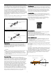

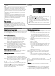
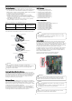

Table Of Contents

3
Clearances
LG Multi F / Multi F MAX air-source units are engineered to be
installed outdoors. These outdoor units require sufficient space to
ensure proper airflow, operation, and maintenance / service
access. When installing outdoor units, allowable service, inlet,
outlet, and space requirements MUST be considered. If the
installation space is too tight around and between the outdoor
units, then the system will not operate properly and it will be
difficult to service. Figures below illustrate clearance requirements
for various installation scenarios for Multi F and Multi F MAX
outdoor units.
Other Outdoor Unit Placement Considerations:
• Noise (Operational and Electrical)
• Site Occupants
• Good Drainage for Condensate, etc.
• Account for Snow Fall Levels
• Prevailing Winds
• Oceanside Applications (Install the outdoor unit on the side of the
building opposite from direct ocean winds. If such an installation
is not possible, then install a concrete windbreaker.)
Multi F Outdoor Unit Service Access and Allowable Clearances.
“L” must be lower than “H”. If a stand is necessary, it must be
contained (not open frame) to prevent the discharge air from
short cycling.
NOTE
!
If the outdoor unit is installed between standard and minimum
clearances, capacity decreases approximately 10%.
NOTE
!
• If the rules for installing Multi F / Multi F MAX outdoor units
(either outside or inside) are not followed correctly, a drop in
outdoor unit fan performance and / or noise can occur, or if
there is insufficient air flow exchange, the system could stop
operating.
• All dimensions are minimum clearances considering airflow
only. Increase as necessary for National Wiring Code or other
code compliance.
• If the installation scenario varies in any way from the samples
provided here or in the complete installation manual, contact
an LG representative for guidance.
NOTE
!
Std. 12"
Min. 4"
Std. 24"
M
in. 10"
Std. 12"
Min. 4"
Min. 40"
Std. 24"
M
in. 10"
Std. 24"
M
in. 10"
Std. 12"
Min
.
4
"
20 inches or less
20 inches or
less
20 inches or less
Min. 12"
Min. 12"
Min. 2
4"
M
i
n. 12"
Min. 12"
Min. 40"
Mi
n. 24"
Max. 20"
Max. 20"
Max. 20"
Min
. 20"
Min. 20"
Min. 40"
Min. 20"
Min. 12"
L
Min. 40"
Min. 4
0"
Max. 20"
Min. 12"
H
Min. 12"
M
i
n. 79"
Min. 24"
Min. 40"
Min. 12"
Min. 24"
Min. 24"
Multi F MAX Outdoor Unit Service Access and Allowable
Clearances.
Obstacles on the suction side
and on both left and right sides.
Obstacles above, on the air
intake side, and on both left and
right sides.
Obstacles above and on the air
discharge side.
Where there are obstacles on
both suction and discharge
sides (discharge side obstacle is
higher than the outdoor unit).
LA
L ≤ H
0 < L ≤ 1/2 H
30 inches
1/2 H < L 40 inches
H < L
Set Stand as: L ≤ H
Where there are obstacles above,
and on both suction and discharge
sides (discharge side obstacle is
lower than the outdoor unit).
Side-by-side series installation. Series installation.
Ratio among H, A, and L.
If placement options are limited because of a lack of ground space,
roof space, a location that meets design requirements, on retrofit
projects where an equipment / mechanical room already exists,
then the outdoor unit MAY be installed in an interior space ONLY
IF specific conditions are fulfilled. For example, if the Multi F / Multi
F MAX outdoor unit is to be installed in an enclosure, it must have
certain design specifications:
Louver Recommendations for Outdoor Unit Enclosures
• Enclosure is a Manual Door Open Type.
• Louver Angle: No More Than 15° Horizontally.
• Space Between Louvers : More than 4 inches (Recommend).
• Louver Shape: Wing or Plane Type. Do not use “S” type
louvers.
• Open Rate, Inlet, Outlet, Air Flow Rate, and Total Opening Rate
must be taken into consideration. See the complete Multi F /
Multi F MAX Outdoor Unit Installation Manual for information.
Maximum 15°
(Recommended)
More than 4 in.
(Recommended)
Louver
Louver Recommendations.