
Quick Setup Guide


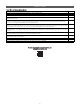
Table Of Contents

10
Installation Checklist
Power Wire and Communications Cables
Description Check
Ground wire was installed and properly terminated at the outdoor unit(s).
Power wiring was connected to a single phase 208-230V source.
The power supplied was clean with voltage fluctuations within specifications (±10% of nameplate).
Power wiring to the Multi F / Multi F MAX outdoor unit was field supplied, solid or stranded, and installed per all local, state,
and NEC requirements.
All communications / connection (power) cable from the Multi F outdoor unit to the indoor units is to be minimum four
conductor, 18 AWG stranded, shielded or unshielded (if shielded, it must be grounded to the chassis of the outdoor unit
only), and must comply with applicable local and national codes.
All power wiring / communication cable to be minimum 16 AWG from the Multi F MAX outdoor unit to the BD unit, and 18
AWG from the branch distribution unit to the indoor units, stranded, shielded or unshielded (if shielded, it must be grounded
to the chassis of the outdoor unit only), and must comply with applicable local and national codes.
Power wiring to the outdoor unit and communication / connection (power) cable from the outdoor unit to the indoor units or
branch distribution units (Multi F MAX only) were separated per manufacturer’s guidelines. These cannot be run in the same
conduit.
Communications / connection (power) cable were run in the same conduit (outdoor unit to indoor unit or branch distribution
unit [Multi F MAX only] as provided in the product installation manual.
Proper communications cable was used between each indoor unit and its zone controller where applicable. No cables were
spliced and no wire nuts are present.
Communication type RS-485–BUS type.
Used appropriate crimping tool to attach ring or fork terminals at all power wiring and control cable terminations.
Only LG-supplied Y-cables were used between grouped indoor units, if applicable.
To access the complete Installation Manual, see :
www.lghvac.com/resources