OWNER’S & INSTALLATION MANUAL AIR CONDITIONER Please read this installation manual completely before installing the product. Installation work must be performed in accordance with the national wiring standards by authorized personnel only. Please retain this installation manual for future reference after reading it thoroughly. Multi F / Multi F MAX This manual is the simplified version of original manual. You can obtain the original manual from website. EN English FR Français MFL71421902 Rev.
Multi F / Multi F MAX Air-Source System Install Tips The following pages present an overview of Multi F / Multi F MAX air-source Variable Refrigerant Flow (VRF) installation concepts, and is intended to supplement the technical and installation information provided with each product. The review of basic operation and maintenance skills must reinforce industry established practices and provide helpful tips to make equipment operation successful.
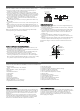
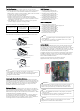
Clearances Where there are obstacles above, and on both suction and discharge sides (discharge side obstacle is lower than the outdoor unit). " x. Ma 20 Min. 40" LG Multi F / Multi F MAX air-source units are engineered to be installed outdoors. These outdoor units require sufficient space to ensure proper airflow, operation, and maintenance / service access. When installing outdoor units, allowable service, inlet, outlet, and space requirements MUST be considered.
Mounting Options Close up of a Bolt Attachment. After an installation area for the outdoor unit(s) is chosen, verify: • The floor surface / chosen location has enough strength to support the weight of the unit(s) and base. • There is enough space for piping and wiring (when installed through the bottom of the unit [Multi F MAX outdoor units only).
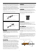
Piping Piping Expansion Under normal operating conditions, the vapor pipe temperature of a Multi F / Multi F MAX system can vary as much as 180°F. With this large variance in pipe temperature, the designer must consider pipe expansion and contraction to avoid pipe and fitting fatigue failures. When a segment of pipe is mounted between two fixed points, provisions must be provided to allow pipe expansion to naturally occur, generally by expansion Loops or U-bends.
Rule for Changes in Piping Direction. Y-branch Installation Alignment Specification. Vertical Up Configuration Vertical Down Configuration Max. 12" 12"–19" Within ± 3° Piping Insulation ALL piping and piping connections in a Multi F / Multi F MAX system must be insulated; a minimum 1/2 inch wall, closed cell with vapor barrier insulation is recommended (follow all local, sate, and national requirements). Insulate all piping separately.
Wiring ! NOTE JIS Screws. • Ensure the power wiring / communication cable shield (if shielded) from the outdoor unit to the indoor units / branch distribution units is properly grounded to the outdoor unit chassis only. Do not ground at any other point. Wiring must comply with all applicable local and national codes. • Use a conduit for the communications / connection (power) cable from the outdoor unit to the indoor units and branch distribution unit(s).
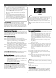
Final Installation Procedures Test Run Procedure 3. Operate the system in cooling mode for 15 to 20 minutes. 4. Evaluate performance as the system runs, verifying the outdoor unit, and all indoor units and branch distribution units (Multi F MAX systems only) are working properly. Make notes as needed to address any issues that might be found. • Check the system refrigerant charge: • Measure the pressure from the gas side service valve. • Measure the indoor unit inlet and outlet air temperatures.
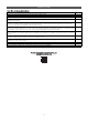
Installation Checklist Major Component Rough-In Description Multi F / Multi F MAX outdoor units are connected properly per local code and the product installation procedures. All literature and bagged accessories have been removed from the fan discharge (ducted and cassette model indoor units). All indoor units and heat recovery units (for Heat Recovery systems only) are installed, properly supported, and located indoors in a non-corrosive environment.
Installation Checklist Power Wire and Communications Cables Description Ground wire was installed and properly terminated at the outdoor unit(s). Power wiring was connected to a single phase 208-230V source. The power supplied was clean with voltage fluctuations within specifications (±10% of nameplate). Power wiring to the Multi F / Multi F MAX outdoor unit was field supplied, solid or stranded, and installed per all local, state, and NEC requirements.
* The following mark and paragraph should be applicable only to the Energy Star certification models. IMPORTANT - This product has been designed and manufactured to meet ENERGY STAR criteria for energy efficiency when matched with appropriate coil components. However, proper refrigerant charge and proper air flow are critical to achieve rated capacity and efficiency. Installation of this product should follow the manufacturer’s refrigerant charging and air flow instructions.