
Install Instructions


69
Electrical System Installation
Due to our policy of continuous product innovation, some specifications may change without notification.
©LG Electronics U.S.A., Inc., Englewood Cliffs, NJ. All rights reserved. “LG” is a registered trademark of LG Corp.
MULTI
F
MAX
MULTI
F
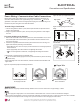
1. Detach the outdoor unit panels by loosening the screws.
2. Remove the control cover (if applicable) by loosening the screws.
3. Remove the conduit knock outs or access holes.
4. Pull the power wiring, and the communications / connection (power) cable into the
outdoor unit (through the conduits, if applicable). Ensure there is enough length to
connect to the terminals on the outdoor unit. Secure any conduits with field-sup-
plied lock nuts.
5. Connect the power wiring, and the communications / connection (power) cable to
the correct terminals on the outdoor unit.
6. Connect communications / connection (power) cable to the correct control board
terminals on the indoor unit (or branch distribution unit[s] if Multi F MAX system).
7. Follow the wiring diagrams on the outdoor unit and indoor units (or branch distri-
bution unit[s]) control covers. Ensure that the terminal board numbers and wiring
color on the outdoor unit matches the terminal number and wiring color on the
indoor unit or branch distribution unit(s).
8. Provide strain relief and help protect the connections by (separately) securing the
wiring / cable to the outdoor unit with the factory-supplied clamps (up to 35 lbs.).
Clamps are included near the terminal block. Zip ties can also be used to hold all
cables in place.
9. For more installation information for specific indoor units, refer to the separate
indoor unit installation manuals on www.lghvac.com.
10. When all connections are complete, reattach the control cover to its original posi-
tion using the screws, then reinstall the outdoor unit panel.
11.After installation is complete, seal any gaps around the wiring in the panel access
holes or the conduits.
Figure 89: Connecting the Power Wiring / Communi-
cations Cables to the Outdoor Unit (LMU180-240HV-
30~36CHV) (Appearances Will Vary).
• Always have a trained technician properly ground the outdoor unit. If the
outdoor unit is not properly grounded, there is a risk of electric shock, phys-
ical injury, or death.
• )DLOXUHWRSURSHUO\LQVWDOOZLULQJFDQUHVXOWLQHOHFWULFVKRFN¿UHSK\VLFDOLQMXU\RU
death.
• Failure to properly provide a NEC-approved earth ground can result in
electric shock, fire, physical injury or death.
• Comply with local and national codes while running the wire from the indoor
unit (and branch distribution units if Multi F MAX system) to the outdoor
unit (size of wire and wiring method, etc). Incorrectly sized wiring will cause
the terminal to overheat, generate a fire, and risk physical injury or death.
• $OOZLULQJFDEOHPXVWEH¿UPO\FRQQHFWHGWRLWVWHUPLQDO/RRVHZLULQJZLOOFDXVH
WKHWHUPLQDOWRRYHUKHDWJHQHUDWHD¿UHDQGULVNSK\VLFDOLQMXU\RUGHDWK
•
Do not allow the wiring / cable to touch refrigerant tubing, the com-
pressor, or any moving parts. It can result in electric shock, fire, physical
injury or death.
• Replace all control box and panel covers. If cover panels are not installed securely,
dust, water and animals will enter the outdoor unit, causing fire, electric shock, and
physical injury or death.
• Ensure the communications / connection (power) cable from the outdoor units to
the indoor / branch distribution units, and the power wiring to the outdoor unit are
separate; otherwise, the outdoor unit operation will be affected by electrical noise
and will malfunction.
• The communications / connection (power) cable from the outdoor unit to the indoor
/ branch distribution units must be separated and isolated from power wiring to the
outdoor unit, computers, elevators, radio and television broadcasting facilities, as
well as medical imaging equipment; otherwise, the outdoor unit operation will be
affected by electrical noise and will malfunction or fail.
• All wiring / cable must be firmly connected to its terminals. Loose wiring will result in unit malfunction.
ELECTRICAL
,QVWDOODWLRQ
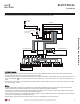
Power supply cabl
(1Ø, 208/230V)
Power Supply Cable
(1Ø, 208/230V)
Connecting cabl
Connecting Cable
Lock nut
(Field Supplied)
Indoor Unit A
Conduit
(Field Supplied)
Indoor Unit B
Indoor Unit C
Indoor Unit D
Conduit
Hole
&RQQHFWLQJWKH&RPPXQLFDWLRQV&RQQHFWLRQ3RZHU&DEOHV
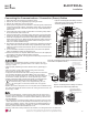
Figure 91: Connecting the Power Wiring / Communica-
tions Cables to the Outdoor Unit (LMU601HV).
Communication / Connection
(Power) Cable Terminal (To
Indoor Units / Branch Distribution
Units)
Power Wiring Terminal
Wiring / Cable
Clamps
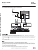
Figure 90: Connecting the Power Wiring / Communications Cables
to the Outdoor Unit (LMU481-541HV).
*
Verify the rubber
bushings are properly
used in the acess
holes.
.
Communication / Connection
(Power) Cable Terminal (To
Indoor Units / Branch Distribution
Units)
Power Wiring Terminal
Wiring / Cable
Clamps
Wiring / Cable
Clamps