website http://www.lgservice.com INSTALLATION MANUAL FRANÇAIS LG Room Air Conditioner ENGLISH LG ESPAÑOL IMPORTANT • Please read this instruction manual completely before installing the product. • When the power cord is damaged, replacement should be performed by authorized personnel only. • Installation work must be performed in accordance with the national wiring standards by authorized personnel only. • Please retain this installation manual for future reference after reading it thoroughly.
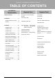
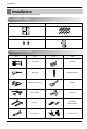
Room Air Conditioner Installation Manual TABLE OF CONTENTS Installation Requirements Safety Precautions............................3 Introduction ........................................9 Required Parts ❏ Four type "A" screws & plastic anchors ❏ Connecting cable Symbols used in this manual..........9 Features ...........................................9 Installation parts ............................10 Installation tools .............................10 ❏ Insulation materials Installation map.........
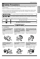
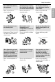
Safety Precautions Safety Precautions This symbol indicates the possibility of death or serious injury. This symbol indicates the possibility of injury or damage to properties only. ■ The meanings of the symbols used in this manual are as shown below. Be sure not to do. Be sure to follow the instruction. ■ Installation Do not use damaged power cords, plugs, or a loose socket. • There is risk of fire or electric shock. Install the panel and the cover of control box securely.
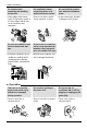
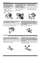
Safety Precautions Be cautious when unpacking and installing the product. • Sharp edges could cause injury. Be especially careful of the case edges and the fins on the condenser and evaporator. Be sure the installation area does not deteriorate with age. • If the base collapses, the air conditioner could fall with it, causing property damage, product failure, and personal injury. For installation, always contact the dealer or an Authorized Service Center.
Safety Precautions Use a dedicated outlet for this appliance. • There is risk of fire or electrical shock. Do not allow water to run into electric parts. Do not store or use flammable gas or combustibles near the air conditioner. • It may cause There is risk of fire, failure of the product, or electric shock. • There is risk of fire or failure of product. Do not place a heater or other appliances near the power cable. • There is risk of fire and electric shock.
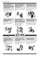
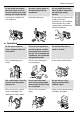
Safety Precautions Do not open the inlet grill of the product during operation. (Do not touch the electrostatic filter, if the unit is so equipped.) When the product is soaked (flooded or submerged), contact an Authorized Service Center. • There is risk of physical injury, • There is risk of fire or eletric electric shock, or product shock. failure. Unplug the appliance before performing cleaning or maintenance. • There is risk of electrical shock.
Safety Precautions • It may cause a problem for your neighbors. Use two or more people to lift and transport the air conditioner. • Avoid personal injury. Do not install the product where it will be exposed to sea wind (salt spray) directly. • It may cause corrosion on the product. Corrosion, particularly on the condenser and evaporator fins, could cause product malfunction or inefficient operation. ■ Operation Do not direct airflow at room occupants. (Don't sit in the draft.
Safety Precautions Always insert the filter securely. Clean the filter every two weeks or more often if necessary. • A dirty filter reduces the efficiency of the air conditioner and could cause product malfunction or damage. Do not insert hands or other objects through the air inlet or outlet while the air conditioner is plugged in. • There are sharp and moving parts that could cause personal injury. Use a firm stool or ladder when cleaning or maintaining the air conditioner.
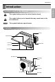
Introduction Introduction This symbol alerts you to the risk of electric shock. This symbol alerts you to hazards that may cause harm to the air conditioner. NOTICE This symbol indicates special notes.
Installation Installation Read carefully, and then follow step by step.
Installation Installation Map ENGLISH NOTICE Installation parts you should purchase. More than 7.9"(20cm) 3.9"(10cm) More than 19.6"(50cm) (Left and right are identical) Sleeve Bushing-Sleeve Putty(Gum Type Sealer) Bend the pipe as close as possible on the wall but be careful so that it may not break. Vinyl tape (Wide) Saddle • To carry out the drainage test, remove the air filter and pour water into the heat exchanger. • Apply after carrying out a drainage test. More than 23.
Installation Confirm The Refrigerant 1. Check the quality label on the indoor and outdoor unit. 2. Make certain that the refrigerant is R-410A. NOTICE THIS PRODUCT CONTAINS R-410A REFRIGERANT 1) Different compressor oil - R-410A(Polyol ester) / R-22(Mineral). - Do not mix the existing mineral oil. - Do not apply used pipe, tools and gauges covered with the existing mineral oil. 2) Absorption of moisture -Compressor’s oil has the high absorption rate of moisture.
Installation Select the best Location 1. Do not have any heat or steam near the unit. 2. Select a place where there are no obstacles in front of the unit. 3. Make sure that condensation drainage can be conveniently routed away. More than 19.6"(50cm) More than 7.9"(20cm) 4. Do not install near a doorway. 5. Ensure that the interval between a wall and the left (or right) of the unit is more than 19.6"(50cm). The unit should be installed as high as possible on the wall, allowing a minimum of 7.
Installation Piping Length and Elevation Pipe Size Capacity (Btu/h) 9k, 12k Suction Evap Ø12.7mm(1/2") Ø6.35mm(1/4") Standard Length m(ft) Max. Elevation B m(ft) Max. length A m(ft) Additional Refrigerant g/m(oz/ft) 7.5(25) 7.5(25) 15(49) 20(0.22) Indoor unit Outdoor unit Outdoor unit A B A Outdoor unit Indoor unit Oil trap B A Indoor unit B If piping length is more than 16.
Installation Preparing Work for Installation ENGLISH Open panel front 1. Pull the upper part of the front panel. 2. Lift up the panel. 3. To detach the front panel, remove the two screws at the lower part. 4. Detach the front panel from the body. 5. To detach the panel, disconnect the connector at the upper part. Panel Front Connector Cover pipe and cover side remove 1. Please remove the screw of the center tuning cover. 2.
Installation Fixing Indoor Unit 1. Attach an Installation guide map on the desired surface. INSTALLATION GUIDE MAP 2. Look at suited horizon by horizontal meter on the horizontal setting line, and fix lightly the map by adhesive tape. Horizontality 3. Make a hole with a diameter of 6mm and depth of 30-35mm by piercing a screw point. IN ST AII AT IO N IN ST AL LA TIO N GU ID EM AP 4. Drill the pierted part as a diameter of 50mm for connecting piping. (In case of piercing rear surface) GU ID EM AP 5.
Installation Flaring Work Cutting the pipes and the cable. 1. Use the piping kit accessory or the pipes purchased locally. 2. Measure the distance between the indoor and the outdoor unit. Copper pipe Slanted Uneven Rough 90° 3. Cut the pipes a little longer than measured distance. 4. Cut the cable 4.9ft(1.5m) longer than the pipe length. Pipe Removing burrs Reamer 1. Completely remove all burrs from the cut cross section of pipe/tube. Point down 2.
Installation Check 1. Compare the flared work with the figure by. Smooth all round Inside is shiny without scratches 2. If a flared section is defective, cut it off and do flaring work again. = Improper flaring = Inclined Surface Cracked Uneven damaged thickness Even length all round Connecting the Piping Indoor Preparing the indoor unit's piping and drain hose for installation through the wall. 1. Route the indoor tubing and the drain hose in the direction of rear left or right Drain hose 2.
Installation Connecting the piping with the indoor unit and drain hose with drain pipe Indoor unit tubing Flare nut Pipings 2. Tighten the flare nut with a wrench. Outside diameter mm inch Ø6.35 1/4 Ø9.52 3/8 Ø12.7 1/2 Torque kgf.cm 180~250 340~420 550~660 Spanner (fixed) Flare nut Torque wrench Connection pipe Indoor unit tubing 3. When extending the drain hose at the indoor unit, install the drain pipe.
Installation CAUTION: Installation Information For right piping. Follow the instruction below. Good case • Press on the upper side of clamp and unfold the tubing to downward slowly. Bad case • Following bending type from left to right may cause damage to the turbing.
Installation Connecting Of Connection thePiping Piping-Outdoor ENGLISH Put a couple drops of refrigerant oil on the face of the flare before assembling taking care not to add any contaminants. Align the center of the pipings and sufficiently tighten the flare nut by hand. Finally, tighten the flare nut with torque wrench until the wrench clicks. • When tightening the flare nut with torque wrench, ensure the direction for tightening follows the arrow on the wrench. Outside diameter mm inch Ø6.35 1/4 Ø9.
Installation Connecting the Cables 1. Remove the cover control from the unit by loosening the screw. 2. Dismount caps on the conduit panel. 3. Temporarily mount the conduit tubes on the conduit panel. 4. Properly connect both the power supply and low voltage lines to the corresponding terminals on the terminal block. 5. Ground the unit in accordance with local codes. 6. Be sure to size each wire allowing several inches longer than the required length for wiring. 7.
Installation Connection method of the connecting cable(Example) WARNING: Loose wiring may cause the terminal to overheat or result in unit malfunction. A fire hazard may also exist. Therefore, be sure all wiring is tightly connected.
Installation CAUTION After the confirmation of the above conditions, prepare the wiring as follows: 1) Never fail to have an individual power circuit specifically for the air conditioner. As for the method of wiring, be guided by the circuit diagram posted on the inside of control cover. 2) The screw which fasten the wiring in the casing of electrical fittings are liable to come loose from vibrations to which the unit is subjected during the course of transportation.
Installation Checking the Drainage ENGLISH To check the drainage. 1. Pour a glass of water on the evaporator. 2. Ensure the water flows through the drain hose of the indoor unit without any leakage and goes out the drain exit. Drain piping 1. The drain hose should point downward for easy drain flow. Downward slope 2. Do not make drain piping like the following.
Installation Forming the Piping Form the piping by wrapping the connecting portion of the indoor unit with insulation material and secure it with two kinds of vinyl tapes. Seal small openings around pipings with a gum type sealer. • If you want to connect an additional drain hose, the end of the drain outlet should be routed above the ground. Secure the drain hose appropriately.
Installation Air Purging The air and moisture remaining in the refrigerant system have undesirable effects as indicated below. 1. Pressure in the system rises. 2. Operating current rises. 3. Cooling(or heating) efficiency drops. 4. Moisture in the refrigerant circuit may freeze and block capillary tubing. 5. Water may lead to corrosion of parts in the refrigeration system. Therefore, after evacuating the system, take a leak test for the piping and tubing between the indoor and outdoor unit.
Installation Soap water method 1. Remove the caps from the 2-way and 3-way valves. 2. Remove the service-port cap from the 3-way valve. 3. To open the 2-way valve turn the valve stem counterclockwise approximately 90°, wait for about 2~3 sec, and close it. 4. Apply a soap water or a liquid neutral detergent on the indoor unit connection or outdoor unit connections by a soft brush to check for leakage of the connecting points of the piping. 5.
Installation Charging ■ Whether the line set is made shorter or longer you must adjust the charge based on how many ft of tubing are either added or removed based on 20g(0.22oz) of R-410A per meter(foot). Pipe Size Capacity (Btu/h) 9k, 12k Suction Evap Ø12.7mm(1/2") Ø6.35mm(1/4") Standard Length m(ft) Max. Elevation B m(ft) Max. length A m(ft) Additional Refrigerant g/m(oz/ft) 7.5(25) 7.5(25) 15(49) 20(0.22) Example: A 30ft line set is used 5 additional ft X 0.22 ounce per foot= add 1.
Installation Panel Front Assembly 1. First, Check the side cover assembly exactly, and fix the power cord in the bottom groove of cover side left. 2. Assemble connecting lead wire with controller, fix the upper part of panel front, and match the lower part of panel front. Panel Front Connector 3. Screw up panel front, and suspend the hook of panel front in the groove.
Installation Test Running ENGLISH 1. Check that all tubing and wiring are properly connected. 2. Check that the gas and liquid side service valves are fully open. Prepare remote controller 1. Remove the battery cover by pulling it according to the arrow direction. 2. Insert new batteries making sure that the (+) and (–) of battery are installed correctly. 3. Reattach the cover by pushing it back into position. NOTICE • Use 2 AAA(1.5volt) batteries. Do not use rechargeable batteries.
Installation NOTICE If the actual pressure is higher than shown, the system is most likely over-charged, and charge should be removed. If the actual pressure are lower than shown, the system is most likely undercharged, and charge should be added. PUMP DOWN This is performed when the unit is relocated or the refrigerant circuit is serviced. Pump Down means collecting all refrigerant into the outdoor unit without the loss of refrigerant. CAUTION: Be sure to perform Pump Down procedure in the cooling mode.
Installation guide at the seaside 1. Air conditioners should not be installed in areas where corrosive gases, such as acid or alkaline gas, are produced. 2. Do not install the product where it could be exposed to sea wind (salty wind) directly. It can result corrosion on the product. Corrosion, particularly on the condenser and evaporator fins, could cause product malfunction or inefficient performance. 3. If outdoor unit is installed close to the seaside, it should avoid direct exposure to the sea wind.
Memo 34 Room Air Conditioner
P/No.