
Engineering Manual

Selecting the Best Location for the Indoor Unit
Follow recommended best practices when choosing an indoor location for
the single zone indoor unit.
Dos
• Follow the table at right for minimum clearance of indoor unit from the
top of the unit to the ceiling.
• Clearance gap between any wall or enclosure and the left or right side
of the unit must be greater than 4 inches. Ensure there is sufficient
maintenance space.
• Unit must be at least 6.5 feet from the floor for adequate clearance.
• Place the unit where drainage can be obtained easily. Condensation
drain must be conveniently routed away from the unit.
• Locate the indoor unit in a location where it can be easily connected to
the outdoor unit within allowable limits.
• Use a metal detector to locate studs in the walls. Anchor unit following
stud location to prevent damage to the wall.
Dont’s
• Do not install the unit near a heat or steam source, or where consid-
erable amounts of oil, iron powder, or flour are used. (These materials
may generate condensate, cause a reduction in heat exchanger effi-
ciency, or the drain to malfunction. If this is a potential problem, install
a ventilation fan large enough to vent out these materials.)
• Ensure there are no obstacles to air circulation around the unit; keep
proper distances from ceilings, doorways, floor, walls, etc.
• Do not install in an area where operation sound will disturb occu-
pants--place the unit where noise prevention is taken into consider-
ation
• Do not install near doorway.
• Avoid installing the unit near high-frequency generators.
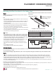
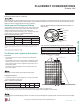
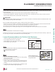
Minimum clearance
from ceiling - “A”
More than 4 inches
More than
4 inches
At least 6.5 feet from the floor
“A” Ceiling Clearance (inches) Indoor Unit Model(s)
5 LAN090HSV5, LAN120HSV5
8 LAN180HSV5, LAN240HSV3
Table 28: Single Zone Art Cool Mirror Indoor Unit Ceiling Clearances.
Figure 43: Single Zone Art Cool Mirror Wall Mount Indoor Unit Clearance
Requirements.
PLACEMENT CONSIDERATIONS
The unit must not be installed where sulfuric acid and ammable or corrosive gases are generated, vented into, or stored. There is risk of re, explo-
sion, and physical injury or death.
The unit may be damaged, may malfunction, and / or will not operate as designed if installed in any of the conditions listed.
• Indoor units (IDUs) must not be placed in an environment where the IDUs may be exposed to harmful volatile organic compounds
(VOCs) or in environments where there is improper air make up or supply or inadequate ventilation. If there are concerns about VOCs in
the environment where the IDUs are installed, proper air make up or supply and/ or adequate ventilation must be provided. Additionally, in
buildings where IDUs will be exposed to VOCs consider a factory-applied epoxy coating to the fan coils for each IDU.
• If the unit is installed near a body of water, the installation parts are at risk of corroding. Appropriate anti-corrosion methods must be taken
for the unit and all installation parts.
Indoor Unit
Installing in an Area Exposed to Unconditioned Air
In some installation applications, areas (floors, walls) in some rooms may be exposed to unconditioned air (room may be above or next to an
unheated garage or storeroom). To countermeasure:
• Verify that carpet is or will be installed (carpet may increase the temperature by three [3] degrees).
• Add insulation between the floor joists.
• Install radiant heat or another type of heating system to the floor.
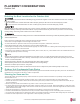
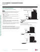
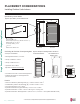
Install a ventilation fan
with sufficient capacity
Heat or steam source
Include enough
distance
Indoor Unit
Figure 44: Installing Near a Heat or Steam Source.
Due to our policy of continuous product innovation, some specications may change without notication.
©LG Electronics U.S.A., Inc., Englewood Cliffs, NJ. All rights reserved. “LG” is a registered trademark of LG Corp.
APPLICATION | 53
Application Guidelines