
Engineering Manual


Due to our policy of continuous product innovation, some specications may change without notication.
©LG Electronics U.S.A., Inc., Englewood Cliffs, NJ. All rights reserved. “LG” is a registered trademark of LG Corp.
50 | PRODUCT DATA
Single Zone Art Cool
TM
Mirror Wall Mount Engineering Manual
Cooling / Heating Correction Factors
For Single Zone Art Cool Mirror Wall Mounted systems, calculate the equivalent length of the liquid line from the outdoor unit to the indoor
unit. Also, determine the elevation difference of the indoor unit above or below the outdoor unit. Find corresponding cooling or heating ca-
pacity correction factors as shown below. Multiply the correction factors by the cooling or heating capacity obtained from the capacity tables
using design conditions. The resultant is the NET cooling or heating capacity.
Refrigerant Line Length Derates
For air-cooled systems, a capacity correction factor may have to be applied to account for the length of the system’s refrigerant pipe. Rate of
change in capacity due to increased piping lengths is shown below.
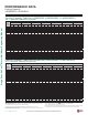
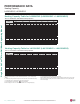
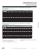
Cooling Capacity Coefficient Factors
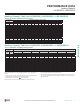
Heating Capacity Coefficient Factors
Table 24: Single Zone Art Cool Mirror Wall Mounted Unit Cooling Capacity Coefcient Factors.
Table 25: Single Zone Art Cool Mirror Wall Mounted Unit Heating Capacity Coefcient Factors.
Piping Length (ft.) 16.4 24.6 32.8 49.2 65.6 82.0 98.4 114.8 131.2 147.6 164.0
Rate of
Capacity
Change (%)
LSU090HSV5 (9,000 Btu/h) 100 100 98.2 94.6 91.1 87.5 - - - - -
LSU120HSV5 (12,000 Btu/h) 100 100 98.2 94.6 91.1 87.5 - - - - -
LSU180HSV5 (18,000 Btu/h) 100 100 99.1 97.3 95.5 93.6 91.8 90.0 - - -
LAU240HSV3 (24,000 Btu/h) 100 100 98.9 96.7 94.4 92.2 90.0 - - - -
Piping Length (ft.) 16.4 24.6 32.8 49.2 65.6 82.0 98.4 114.8 131.2 147.6 164.0
Rate of
Capacity
Change (%)
LSU090HSV5 (9,000 Btu/h) 100 100 99.1 97.3 95.6 93.8 - - - - -
LSU120HSV5 (12,000 Btu/h) 100 100 99.1 97.3 95.6 93.8 - - - - -
LSU180HSV5 (18,000 Btu/h) 100 100 99.5 98.6 97.7 96.8 95.9 95.0 - - -
LAU240HSV3 (24,000 Btu/h) 100 100 99.4 98.3 97.2 96.1 95.0 - - - -
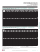
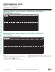
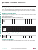
Equivalent Piping Length for Piping Components
Component Size (Inches)
Elbow (ft.)
1/4 3/8 1/2 5/8 3/4 7/8 1 1-1/8 1-1/4 1-3/8 1-1/2 1-5/8 1-3/4 2-1/8
0.5 0.6 0.7 0.8 1.2 1.3 1.5 1.6 1.8 2.0 2.1 2.3 2.5 2.8
Table 26: Equivalent Piping Length for Elbows.
Altitude Correction Factor
The impact of air density must be considered on systems installed at a significant altitude above sea level, therefore, locally accepted alti-
tude correction factors must be applied.
EQUIPMENT SELECTION PROCEDURE
Correction Factors