
Engineering Manual

Due to our policy of continuous product innovation, some specications may change without notication.
©LG Electronics U.S.A., Inc., Englewood Cliffs, NJ. All rights reserved. “LG” is a registered trademark of LG Corp.
34 | PRODUCT DATA
Single Zone Art Cool
TM
Mirror Wall Mount Engineering Manual
Controller Options
Single Zone Art Cool Mirror Wall Mount systems include a wireless handheld remote controller (Model
No. AKB74955602), but optional LG-suppled wired controllers are available. See “Functions, Controls,
Options”, or contact an LG representative for more information.
Wireless Handheld Remote Controller features:
• Display Panel: Displays operation conditions.
• On / Off Button: Turns system operation on and off.
• Mode Button: Selects the operation mode: Cooling, Heating, Auto, Dry
(Dehumidification), or Fan.
• Temp Up / Down Buttons: Adjusts the desired room temperature in the different modes.
• Fan Speed Button: Sets desired fan speed.
• Reset: Initializes the handheld remote control settings.
Figure 36: AKB74955602 Wire-
less Handheld Remote Controller.
Buttons may differ depending on
model type.
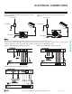
Verify the connectors are properly inserted.
C/BOX Cable (Plug type)
Extension cable
To Indoor Unit
CN-REMO
Terminal
TEMP
FAN
SPEED
OPER
MODE
Figure 37: PZCWRC1 LG Wired Remote Extension Cable
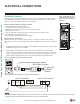
Wired Controller Connections
Optional controllers (see “Functions, Controls, Options”, or contact an LG representative for more
information) can connect to the Single Zone Art Cool Mirror Wall Mount indoor unit in one of two different
ways.
1. LG Wired Remote Extension Cable with Molex plug (PZCWRC1; sold separately) that connects to the
CN-REMO terminal on the indoor unit PCB.
2. Field-supplied controller cable that connects to the indoor unit terminal block (must be at least
UL2547 or UL1007, and at least FT-6 rated if local electric and building codes require plenum cable
usage). Communication cable from indoor unit to remote controller(s) is to be 22 AWG, 3-conductor,
twisted, stranded, unshielded. Wiring must comply with all applicable local and national codes.
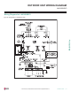
Figure 38: Wired Controller Connection on the Indoor Unit Terminal Block.
Display
Screen
Button
*
*
*
RESET
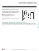
ELECTRICAL CONNECTIONS
Indoor Unit Terminal Block
1(L1 )2(L2)
GND
3
Outdoor Unit Terminal Block
GND
GRN /
YLW
BR
BL
RD
3
CN-REMO
When using eld-supplied controller cable, make sure to connect the yellow to yellow (communications wire), red to red (12V power wire), and black
to black (ground wire) terminals from the remote controller to the indoor unit terminal blocks.