
Engineering Manual

Due to our policy of continuous product innovation, some specications may change without notication.
©LG Electronics U.S.A., Inc., Englewood Cliffs, NJ. All rights reserved. “LG” is a registered trademark of LG Corp.
PRODUCT DATA | 25
Product Data
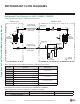
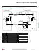
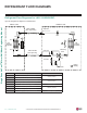
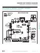
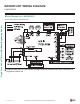
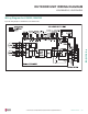
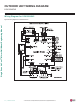
REFRIGERANT FLOW DIAGRAMS
Refrigerant Flow Diagrams for LAN / LSU180HSV5
Table 10: Single Zone Art Cool Mirror Wall Mount LA180HSV5 Thermistor Details.
Thermistor Description PCB Connector
TH1
Indoor air temperature thermistor
CN-TH1 (Indoor)
TH2
Evaporator inlet temperature thermistor
TH3
Evaporator middle temperature thermistor CN-TH3 (Indoor)
TH4
Evaporator outlet temperature thermistor
CN-TH2 (Indoor)
TH5
Water level sensor (optional)
TH6
Outdoor air temperature thermistor
CN-TH1 (Outdoor)
TH7
Condensing temperature thermistor
TH8
Discharge pipe temperature thermistor CN-TH2 (Outdoor)
Figure 24: Refrigerant Flow Diagram for LA180HSV5 Units.
Field Pipin g
(Copper Tubing)
Field Pipin g
(Copper Tubing)
M
M
Heat
Exchanger
(Evaporator)
Heat
Exchanger
(Condenser)
Compressor
3-Way Valve
Valve
Reversing
Indoor Unit Outdoor Unit
: Cooling
: Heating
EEV
Th1
Th4
Th3
Th6
Th7
Th8
Liquid Side
Vapor Side
3-
Way Valve
Th5
Th2
Accumulator
Ø5/8 Inches
Ø3/8 Inches