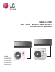
SINGLE-ZONE ART COOLTM MIRROR WALL MOUNT INSTALLATION MANUAL Models: LA090HSV5 LA120HSV5 LA180HSV5 LA240HSV3
PROPRIETARY DATA NOTICE This document, as well as all reports, illustrations, data, information, and other materials are the property of LG Electronics U.S.A., Inc., and are disclosed by LG Electronics U.S.A., Inc., only in confidence. This document is for design purposes only. Do not throw away, destroy, or lose this manual. Please read carefully and store in a safe place for future reference. Content familiarity required for proper installation.
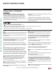
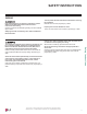
SAFETY INSTRUCTIONS The instructions below must be followed to prevent product malfunction, property damage, injury or death to the user or other people. Incorrect operation due to ignoring any instructions will cause harm or damage. The level of seriousness is classified by the symbols described below. TABLE OF SYMBOLS DANGER This symbol indicates an imminently hazardous situation which, if not avoided, will result in death or serious injury.
SAFETY INSTRUCTIONS INSTALLATION - CONTINUED Single Zone Art CoolTM Mirror Wall Mount Installation Manual If the air conditioner is installed in a small space, take measures to prevent the refrigerant concentration from exceeding safety limits in the event of a refrigerant leak. Consult the latest edition of ASHRAE (American Society of Heating, Refrigerating, and Air Conditioning Engineers) Standard 15.
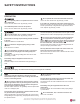
SAFETY INSTRUCTIONS WIRING High voltage electricity is required to operate this system. Adhere to the National Electrical Codes and these instructions when wiring. Improper connections and inadequate grounding can cause accidental injury or death. Turn the power off at the nearest disconnect before servicing the equipment. Electrical shock can cause physical injury or death. Properly size all circuit breakers or fuses. There is risk of fire, electric shock, explosion, physical injury or death.
SAFETY INSTRUCTIONS OPERATION Do not operate the disconnect switch with wet hands. Do not provide power to or operate the unit if it is flooded or submerged. Single Zone Art CoolTM Mirror Wall Mount Installation Manual There is risk of fire, electric shock, physical injury or death. Use a dedicated power source for this product. There is risk of fire, electric shock, physical injury or death. There is risk of fire, electric shock, physical injury or death.
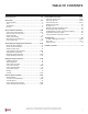
TABLE OF CONTENTS Safety Instructions.............................................................................. 3-6 General Data...................................................................................... 8-11 Unit Nomenclature................................................................................ 8 Parts..................................................................................................... 9 Specifications................................................................
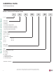
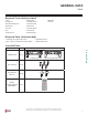
GENERAL DATA Unit Nomenclature Indoor Units and Outdoor Units L A N 180 H Single Zone Art CoolTM Mirror Wall Mount Installation Manual L = LG Frame Type: A: Art Cool™ S: Standard C: Four-Way Ceiling-Cassette D: Ceiling-Concealed Duct (Low Static) H: Ceiling-Concealed Duct (High Static) V: Vertical-Horizontal Air Handling N: Indoor Unit U: Outdoor Unit No N or U: System Capacity (Mbh) 9=9 12 = 12 18 = 18 24 = 24 36 = 36 42 = 42 48 = 48 System Type: H = Heat Pump Style: SV = High Efficiency Inverter
GENERAL DATA Parts Required Tools (field provided) • • • • • • • Level Screwdriver Electrical lineman pliers Electric drill Hole saw Drill Flaring tool set • • • • • • • Tubing cutter Tube/pipe reamer Torque wrenches Allen wrench Gas-leak detector Thermometer Measuring Tape • Multimeter • Ammeter Required Parts (field provided) • Connecting cable (power and control) • Pipes - vapor line and liquid line, with insulation • Insulated drain hose • Additional drain hose Included Parts Quantity Installa
GENERAL DATA Specifications Single Zone Art CoolTM Mirror Wall Mount Installation Manual Table 1: Single Zone Art Cool Mirror Wall Mount System Specifications.
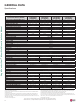
GENERAL DATA Electrical Data Electrical Data Table 2: Single Zone Art Cool Mirror Wall Mount Electrical Data. Indoor Unit Voltage Range Outdoor Unit Hertz Voltage (Min. to Max.) LAN090HSV5 LSU090HSV5 LAN120HSV5 LSU120HSV5 LAN180HSV5 LSU180HSV5 60 208 - 230 187 - 253 LAN240HSV3 LAU240HSV3 Voltage tolerance is ±10%. Maximum allowable voltage unbalance is 2%. MCA = Minimum Circuit Ampacity. Maximum Overcurrent Protection (MOP) is calculated as follows: (Largest motor FLA x 2.
GENERAL INSTALLATION GUIDELINES Outdoor Unit Location Selection Selecting the Best Location for the Outdoor Unit DANGER Do not install the unit in an area where combustible gas may generate, flow, stagnate, or leak. These conditions can cause a fire, resulting in bodily injury or death. • Do not install the unit in a location where acidic solution and spray (sulfur) are often used as it can cause bodily injury or death.
GENERAL INSTALLATION GUIDELINES Outdoor Unit Location Selection Planning for Snow and Ice, continued. When deciding on a location to place the outdoor unit, be sure to choose an area where run-off water from defrost cycle will not accumulate and freeze on sidewalks or driveways, which may create unsafe conditions. Properly install and insulate any drain hoses to prevent the hose from freezing, cracking, leaking, and causing unsafe conditions from frozen condensate.
GENERAL INSTALLATION GUIDELINES Outdoor Unit Location Selection Oceanside Applications Figure 2: Oceanside Placement Using Windbreak. Use of a Windbreak to Shield from Sea Wind Windbreak Single Zone Art CoolTM Mirror Wall Mount Installation Manual Ocean winds may cause corrosion, particularly on the condenser and evaporator fins, which, in turn could cause product malfunction or inefficient performance. • • • • • • Avoid installing the outdoor unit where it would be directly exposed to ocean winds.
GENERAL INSTALLATION GUIDELINES Required Outdoor Unit Clearances Minimum Clearance Requirements for Single Fan Outdoor Units Proper clearance for the outdoor unit coil is critical for proper operation. When installing the outdoor unit, consider service, inlet and outlet, and minimum allowable space requirements as illustrated in the diagrams below. Specific clearance requirements in the diagram below are for single fan outdoor units.
GENERAL INSTALLATION GUIDELINES Required Outdoor Unit Clearances / Mounting Rigging and Lifting Instructions WARNING Wear protective gloves and safety goggles when handling equipment. Sharp edges may cause personal injury. Single Zone Art CoolTM Mirror Wall Mount Installation Manual Dispose of the packing materials safely. • Packing materials, such as nails and other metal or wooden parts, may cause puncture wounds or other injuries.
GENERAL INSTALLATION GUIDELINES Outdoor Unit Mounting Concrete Platform Specifications • Concrete foundations must be made of one part cement, two parts sand, and four parts gravel. • The surface of the foundation must be finished with mortar with rounded edges, and weatherproofed. Figure 6: Example of Using an Insert for a Hole in a Reinforced Concrete Beam. Figure 7: Close up of Bolt Attachment.
GENERAL INSTALLATION GUIDELINES Required Indoor Unit Clearances Follow recommended best practices when choosing an indoor location for the single zone indoor unit. Figure 10: Single Zone Art Cool Mirror Wall Mount Indoor Unit Clearance Requirements. More than 4 inches Single Zone Art CoolTM Mirror Wall Mount Installation Manual Dos • Follow the table at right for minimum clearance of indoor unit from the top of the unit to the ceiling.
GENERAL INSTALLATION GUIDELINES Indoor Unit Mounting Drilling the Piping Hole in the Wall Figure 12: Drilling Piping Hole. WALL Follow all piping clearance recommendations. 1. Using a 2-9/16 inch hole core drill bit, drill a hole at either the right or left side of the wall mounting, pre-chosen following installation guidelines and application needs. • The slant of the hole must be 3/16” to 5/16” from level with the slant being upward on the indoor unit side and downward on the outdoor unit side. 2.
GENERAL INSTALLATION GUIDELINES Indoor Unit Mounting Single Zone Art CoolTM Mirror Wall Mount Installation Manual Removing the Indoor Unit Bottom Cover (HSV5) Figure 15: Indoor Unit with the Bottom Cover On (Bottom View; Appearances May Vary Depending on Indoor Unit Model). To access the indoor unit piping port connections, terminal block, and to make the indoor unit installation procedure easier, it is recommended that the bottom cover be removed first. 1.
GENERAL INSTALLATION GUIDELINES Indoor Unit Mounting Mounting the Indoor Unit to the Installation Plate 1. Position the indoor unit onto the upper portion of the installation plate. Figure 21: Attaching the Indoor Unit to the Installation Plate. 2. Engage the hooks at the top of the indoor unit with the upper edge of the installation plate (number of hooks depends on model type). 3. Ensure the hooks are properly seated on the installation plate by shaking the indoor unit left and right.
GENERAL INSTALLATION GUIDELINES Indoor Unit Mounting Preparing for Piping / Electrical Connections Single Zone Art CoolTM Mirror Wall Mount Installation Manual 1. To prepare the indoor unit for piping and electrical installation, disengage bottom on indoor unit from installation plate by reversing Steps 6, 5, and 4 from the previous procedure, if those procedures have been performed. 2. Unsnap the piping / drain hose holder (L-bracket) out from the indoor unit chassis.
REFRIGERANT SAFETY STANDARDS / DEVICE CONNECTION LIMITATIONS Refrigerant Safety Standards ASHRAE Standards 15-2010 and 34-2010 address refrigerant safety and the maximum allowable concentration of refrigerant in an occupied space. Refrigerant will dissipate into the atmosphere, but a certain volume of air is required to safely dissipate the refrigerant. For R410A refrigerant, the maximum allowable concentration of refrigerant is 26 lbs.
SELECTING FIELD SUPPLIED PIPING Selecting Field-Supplied Copper Piping Single Zone Art CoolTM Mirror Wall Mount Installation Manual Always follow local codes when selecting and installing copper pipe and piping system components. Approved piping for use with LG Single Zone products will be marked “R410 RATED” along the length of the pipe. Piping wall thickness must meet local code requirements and be approved for a maximum operating pressure of 551 psi.
COPPER EXPANSION AND CONTRACTION Copper Expansion and Contraction Under normal operating conditions, the vapor pipe temperature of a Duct Free System can vary as much as 280°F. With this large variance in pipe temperature, the designer must consider pipe expansion and contraction to avoid pipe and fitting fatigue failures. If the pipe is mounted in free air space, no natural restriction to movement is present if mounting clamps are properly spaced and installed.
COPPER EXPANSION AND CONTRACTION Single Zone Art CoolTM Mirror Wall Mount Installation Manual Table 11: Linear Thermal Expansion of Copper Tubing in Inches. Pipe Length1 10 20 30 40 50 60 70 80 90 100 120 140 160 180 1 35° 0.04 0.08 0.12 0.16 0.20 0.24 0.28 0.32 0.36 0.40 0.48 0.56 0.64 0.72 40° 0.04 0.08 0.12 0.16 0.20 0.24 0.28 0.32 0.36 0.40 0.48 0.56 0.64 0.72 45° 0.05 0.10 0.15 0.20 0.25 0.30 0.35 0.40 0.45 0.50 0.60 0.70 0.80 0.90 50° 0.06 0.12 0.18 0.24 0.30 0.36 0.42 0.48 0.54 0.60 0.72 0.
PIPING HANDLING Piping Materials and Handling Keep Pipes Capped While Storing. Pipes used for the refrigerant piping system must include the specified thickness, and the interior must be clean. While handling and storing, do not bend or damage the pipes, and take care not to contaminate the interior with dust, moisture, etc. No moisture should be inside the piping. Moisture Possible - Significant hydrolysis of refrigerant oil. Problems - Refrigerant oil degradation. - Poor insulation of the compressor.
REFRIGERANT SYSTEM ENGINEERING Proper system operation depends on the installer using utmost care while assembling the piping system. The following pages are an overview of best practices when installing the refrigerant piping system. Single Zone Art CoolTM Mirror Wall Mount Installation Manual LG Electronics U.S.A.,Inc.
REFRIGERANT SYSTEM ENGINEERING Obstacles Figure 28: Installing Piping Above and Below an Obstacle. 3X MINIMUM X X 3X MINIMUM Above an obstacle Below an obstacle Pipe Supports Figure 29: Pipe Hanger Details. A properly installed pipe system must be adequately supported to avoid pipe sagging. Sagging pipes become oil traps that lead to equipment malfunction. Pipe supports must never touch the pipe wall; supports must be installed outside (around) the primary pipe insulation jacket.
REFRIGERANT SYSTEM ENGINEERING Pipe Sleeves at Penetrations LG requires that all pipe penetrations through walls, floors, and pipes buried underground be properly insulated and routed through an appropriate wall sleeve of sufficient size to prevent compression of refrigerant pipe insulation and free movement of the pipe within the sleeve. Use 4”+ curved sheet metal saddles between the bottom surface of the pipe and the bottom surface of the penetration.
FLARING AND BRAZING PROCEDURES Flaring and Brazing Procedures One of the main causes of refrigerant leaks is a defective connection. For LG HVAC systems, the installer needs to know how perform both flared and brazed connections successfully. • During installation, it is imperative to keep the piping system free of contaminants and debris such as copper burrs, slag, or carbon dust. • Do not use kinked pipe caused by excessive bending in one specific area on its length. Flaring Procedure 1.
FLARING AND BRAZING PROCEDURES Single Zone Art CoolTM Mirror Wall Mount Installation Manual Tightening the Flare Nuts Tightening Torque for Flare Nuts. Pipe Size (in. O.D.) Outside Diameter (mm) Tightening Torque (ft-lbs.) 13.0 - 18.0 1/4 6.35 9.52 24.6 - 30.4 3/8 39.8 - 47.7 1/2 12.7 45.4 - 59.3 15.88 5/8 71.5 - 87.5 19.05 3/4 1. When connecting the flare nuts, coat the flare (outside only) with polyvinyl ether (PVE) refrigeration oil only.
REFRIGERANT PIPING CONNECTIONS Installation Overview Installation Figure 34: Installation and Piping Connection Overview. Single Zone Wall-Mounted systems are one-to-one systems. There is a direct piping connection between the outdoor unit and the indoor unit. The figure at right illustrates the basic pipe connections between the outdoor and indoor unit. Refer to the illustration when proceeding with pipe connections.
REFRIGERANT PIPING CONNECTIONS Special Applications Special Applications Figure 35: Special Applications. If an additional drain hose is necessary, the end of drain outlet must be routed above the ground. Secure the drain hose appropriately. Single Zone Art CoolTM Mirror Wall Mount Installation Manual When the Outdoor Unit is Installed Below the Indoor Unit: 1.
REFRIGERANT PIPING CONNECTIONS Outdoor Unit Connections Outdoor Unit Connections 1. Remove the piping cover or piping / control box cover (configuration depends on outdoor unit model) from the unit by loosening the fastening screws. 2. Align the center of the refrigerant piping and corresponding connection as shown. 3. Refer to the figures below for liquid and gas (vapor) piping attachments onto the outdoor unit. 4. Place a couple of drops of PVE refrigerant oil on outside of the flare before assembling.
REFRIGERANT PIPING CONNECTIONS Indoor Unit Connections for HSV5 Units Single Zone Art CoolTM Mirror Wall Mount Installation Manual Removing the Indoor Unit Bottom Cover To access the indoor unit piping port connections, and to make the indoor unit installation procedure easier, it is recommended that the bottom cover be removed first. 1. Unsnap the bottom cover at its top left and right sides (Location 1). Figure 44: Removing the Bottom Cover. Figure 45: Removing the Bottom Cover, Alternate View. 2.
REFRIGERANT PIPING CONNECTIONS Indoor Unit Connections for HSV5 Units • Do not bend the piping directly backwards or to the left or right sides without bending it downward first; this may damage the indoor unit piping. • Do not forcibly press the refrigerant piping onto the bottom frame or the front grille; this may damage the indoor unit piping and / or indoor unit frame. • Ensure the piping is straight. Do not kink the piping; this may damage the indoor unit and piping.
REFRIGERANT PIPING CONNECTIONS Indoor Unit Connections for HSV5 Units Piping Installation When Piping is on the Right Side Figure 49: Piping Installation When Piping is on the Right Side. Right Side Piping Single Zone Art CoolTM Mirror Wall Mount Installation Manual See the Electrical System Installation section for information on how to connect the communication / connection (power) wiring from the outdoor unit. Tape Connection Cable Drain Hose Piping 1.
REFRIGERANT PIPING CONNECTIONS Indoor Unit Connections for HSV3 Units Piping to Indoor Unit (HSV3) To access the indoor unit piping port connections, terminal block, and to make the indoor unit installation procedure easier, it is recommended that the bottom cover be removed first. 1. 2. 3. 4. 5. 6. Pull the screw cap(s) at the bottom of the indoor unit. Unscrew the two (2) or three (3) screws (depending on the indoor unit model) at the bottom of the chassis cover.
REFRIGERANT PIPING CONNECTIONS Outdoor Unit Drain Piping / Indoor Unit Drain Hose Outdoor Unit Condensate Drain Piping Installation Single Zone Art CoolTM Mirror Wall Mount Installation Manual Depending on the installation location, it may be necessary to install factory-supplied drain plug(s). For information in reference to outdoor unit placement, see the “Outdoor Unit Location Selection” section. Figure 57: LSU090-120HSV5 Drain Component Locations.
REFRIGERANT PIPING CONNECTIONS Indoor Unit Drain Hose • Insert the drain hose >2 inches so it won’t pull out of the field-supplied drain pipe. • Avoid piping the drain hose as shown in the diagrams in the Figure below. These methods are incorrect and can cause leaks at the indoor unit site. Figure 59: Inserting the Drain Hose >2 inches Into the Field-Supplied Drain Pipe. Insert the drain hose >2 inches so it won’t be pulled out of the fieldsupplied drain pipe.
REFRIGERANT PIPING CONNECTIONS Checking the Indoor Unit Drain Hose for Leaks Figure 62: Checking for Leaks at the Indoor Unit. Single Zone Art CoolTM Mirror Wall Mount Installation Manual 1. Pour a glass of water on the evaporator. 2. Verify that the water flows appropriately through and out of the drain hose without any leaks.
INSULATION Refrigerant Piping System Insulation For information regarding insulation for underground or penetration situations, see the “General Refrigerant Piping System Information” section. All refrigerant piping from the outdoor unit to the indoor units must be insulated correctly for safety and usage.
INSULATION Single Zone Art CoolTM Mirror Wall Mount Installation Manual Minimum Refrigerant Pipe Ethylene Propylene Diene Methylene (EPDM) Insulation Wall Thickness Requirements • Do not insulate gas and liquid pipes together as this can result in pipe leakage and malfunction due to extreme temperature fluctuations. • Always properly insulate the piping. Insufficient insulation will result in condensation, reduced heating/cooling performance, etc.
ELECTRICAL SYSTEM INSTALLATION Safety Guidelines / Connections and Specifications • Consider ambient conditions (temperature, direct sunlight, inclement weather, etc.) when selecting, installing, and connecting the power wiring. • Properly ground the Single Zone outdoor and indoor unit. Improperly connected ground wire can cause communication problems from electrical noise and motor current leakage. Ground wiring must always be installed by a trained technician.
ELECTRICAL SYSTEM INSTALLATION Connections and Specifications Power Wiring / Communication Cable Connections, continued 1. Remove the JIS terminal screws from the (outdoor unit or indoor unit) terminal plate with a JIS screwdriver. (See information about LG terminal connections on the next page.) 2. Position the ring terminal around the terminal, place the terminal screw in the ring, and tighten to the terminal plate using a JIS screwdriver.
ELECTRICAL SYSTEM INSTALLATION Connections and Specifications Power Supply / Power Wiring Specifications From Outdoor Unit To Indoor Unit GN Refer to Electrical Data table for ampere ratings. Properly size all circuit breakers / fuses, wiring and field provided components/Yper L local codes. There is risk of fire, electric shock, explosion, physical injury or death.
"± /16 ELECTRICAL SYSTEM INSTALLATION Power Wiring, Ground Connections and Specifications " 1/8 7 to Outdoor Unit GN /YL Single Zone Art CoolTM Mirror Wall Mount Installation Manual Communication / Connection (Power) Cable Specifications from Outdoor 13/ 16" Unit to Indoor Unit Figure 76: Typical Single Zone Outdoor Unit to Indoor Unit Wiring and • For communication / connection (power) wires between the Single Zone outdoor unit and the indoor unit for lengths up to 130 feet, use a minimum 18 gaug
ELECTRICAL SYSTEM INSTALLATION Connections and Specifications Power / Communication System Diagrams For Wiring Lengths Up to 130 Feet Figure 78: Typical LA090-120HSV5 Power / Communication System Diagram For Wiring Lengths Up to 130 Feet. Figure 79: Typical LA180HSV5 Power / Communication System Diagram For Wiring Lengths Up to 130 Feet. 208/230 VAC Electrical System Installation Figure 80: Typical LA240HSV3 Power / Communication System Diagram For Wiring Lengths Up to 130 Feet.
ELECTRICAL SYSTEM INSTALLATION Connections and Specifications Power / Communication System Diagrams For Wiring Lengths GREATER THAN 130 Feet Single Zone Art CoolTM Mirror Wall Mount Installation Manual Figure 81: Typical LA090-120HSV5 Power / Communication System Diagram For Wiring Lengths GREATER THAN 130 Feet. Figure 82: Typical LA180HSV5 Power / Communication System Diagram For Wiring Lengths GREATER THAN 130 Feet.
ELECTRICAL SYSTEM INSTALLATION Controller Options Controller Options Figure 85: AKB74955602 Wireless Handheld Remote Controller. Buttons may differ depending on model type. Single Zone Art Cool Mirror Wall Mount systems include a wireless handheld remote controller (Model No. AKB74955602), but optional LG-suppled wired controllers are available. See “Functions, Controls, Options”, or contact an LG representative for more information.
ELECTRICAL SYSTEM INSTALLATION Indoor Unit Electrical Connections Connecting Indoor Unit Electrical Wiring for HSV5 Units Single Zone Art CoolTM Mirror Wall Mount Installation Manual • Verify that main power to the unit is completely off before proceeding with these steps as there is a risk of electrical shock, bodily injury, and / or death. • Follow all safety and warning information outlined at the beginning and throughout this manual.
ELECTRICAL SYSTEM INSTALLATION Indoor Unit Electrical Connections Connecting Indoor Unit Electrical Wiring for HSV5 Units, continued. 7. Choice of the cable path out of the indoor unit and to the outdoor unit depends on refrigerant piping / drain hose installation: left side piping, following back of indoor unit; right side piping, through the knockout hole; or rear piping. Figure 93: Cable / Refrigerant Piping / Drain Hose Installation Options.
ELECTRICAL SYSTEM INSTALLATION Indoor Unit Electrical Connections Connecting Indoor Unit Electrical Wiring for HSV3 Units Single Zone Art CoolTM Mirror Wall Mount Installation Manual • Verify that main power to the unit is completely off before proceeding with these steps as there is a risk of electrical shock, bodily injury, and / or death. • Follow all safety and warning information outlined at the beginning and throughout this manual.
ELECTRICAL SYSTEM INSTALLATION Indoor Unit Electrical Connections Connecting Indoor Unit Electrical Wiring for HSV3 Units, continued 5. When done, reattach the bottom panel to the indoor unit, being careful to align panel using the rear tabs. 6. Using a screwdriver, reattach the screws to the bottom panel and secure. 7. Once screws are in place, re-snap the latches over the screws.
ELECTRICAL SYSTEM INSTALLATION Outdoor Unit Electrical Connections Single Zone Art CoolTM Mirror Wall Mount Installation Manual Connecting Outdoor Unit Wiring • Verify that main power is completely off and that no power is going through the Single Zone system before proceeding with these steps. Follow all safety and warning information outlined at the beginning of this manual. Failure to do so may cause electric shock, bodily injury and / or death.
ELECTRICAL SYSTEM INSTALLATION Outdoor Unit Electrical Connections Connecting Outdoor Unit Wiring, continued. Figure 103: Outdoor Unit Conduit Holes. Figure 102: Example of Conduit. LSU090-120HSV5 Do not install power wiring to the outdoor unit and the communication / connection (power) cable to the indoor unit in the same conduit. Use separate conduits. Communication problems may occur. Loose, damaged, or cracked wires may cause electric shock, bodily injury and / or death.
FINAL INSTALLATION PROCEDURES Triple Leak / Pressure Test Triple Leak / Pressure Test Single Zone Art CoolTM Mirror Wall Mount Installation Manual After the refrigerant piping installation is complete, perform a triple leak / pressure test. Triple leak / pressure test is performed between the outdoor unit and indoor unit to verify that refrigerant can flow through the system without danger of leaks or pressure losses.
FINAL INSTALLATION PROCEDURES Triple Leak / Pressure and Deep Evacuation Tests Triple Leak / Pressure Check Procedure, continued. The bubble solution must be a solution designed for refrigerant leak testing. Common soap solution must never be used on refrigerant piping as those contain chemicals that could corrode copper and brass, and cause product malfunction. 7. If the pressure does NOT drop for one (1) hour, the system passes the test. 8. If the pressure drops, there is a leak and it must be found.
FINAL INSTALLATION PROCEDURES Deep Evacuation and Triple Evacuation Tests Deep Evacuation Procedure, continued. Figure 107: EvacuationProcedureDiagram. Indoor Unit Single Zone Art CoolTM Mirror Wall Mount Installation Manual 3. Evacuate to static micron level ≤500 for at least one (1) hour. 4. Micron level must remain ≤500 for two (2) hours. If the vacuum gauge rises and stops, the system may contain moisture; therefore, it will be necessary to repeat the steps of vacuum break and drying.
FINAL INSTALLATION PROCEDURES Triple Evacuation Test Triple Evacuation Procedure Steps 1. If this procedure is performed shortly after the leak / pressure test, the cap and core on the gas (vapor) suction Schrader port must have already been removed, and the manifold must already be connected. If the procedure was not performed shortly after the leak / pressure test, make sure to remove the cap and core on the gas (vapor) suction Schrader port.
FINAL INSTALLATION PROCEDURES Refrigerant Trim Charge, Finishing the Job Refrigerant Trim Charge Single Zone Art CoolTM Mirror Wall Mount Installation Manual The single zone system may need an additional refrigerant charge if the installed piping lengths are greater than the “piping length (no additional refrigerant, ft.) specification” listed in the product tables. See the product sections in the engineering and installation manuals.
FINAL INSTALLATION PROCEDURES Reattaching the Indoor Unit Bottom Cover Reattaching the Indoor Unit Bottom Cover Reattach the indoor unit bottom cover after all other installation procedures are complete. Figure 108: Close Up of Bottom Cover Connections (Appearances May Vary Depending on Indoor Unit Model). Top Snaps 1. If ON, shut power OFF to the system. C-Hooks 2.
FINAL INSTALLATION PROCEDURES Air Filter Disassembly and Assembly Figure 113: Disassembling the Air Filter (Appearances May Vary Depending on Indoor Unit Model). Air Filter Disassembly and Assembly Air Filter Disassembly 1. Turn power off to the system. 2. Lifting the Air Filter by the Handles. Single Zone Art CoolTM Mirror Wall Mount Installation Manual 2. Find the handles located at the top-front of the air filter molded into the plastic frame support. 3.
FINAL INSTALLATION PROCEDURES Installing Batteries, Test Run, Performance Evaluation Installing Batteries into the Handheld Remote Controller For information on using the handheld remote controller, refer to its owner’s manual. 1. The remote controller needs two AAA (1.5V) batteries for operation. Remove the battery cover from the back of the remote controller by pushing the tab down in the direction seen at right. Figure 115: Installing the Remote Controller Batteries. Battery Cover Tab Battery Cover 2.
FINAL INSTALLATION PROCEDURES Installer Mode, Heating Only Mode Installer Mode It will be necessary to switch to Installer mode if the system needs to operate in Heating Only or Cooling Only modes, or the Pump Down procedure needs to be performed. Figure 118: Using the Handheld Controller to Change System to Installer Mode. To Enter Installer Mode: Single Zone Art CoolTM Mirror Wall Mount Installation Manual 1. Press the Reset and “A” buttons. A very slender tool is needed to access the Reset button.
FINAL INSTALLATION PROCEDURES Cooling Only Mode, Pump Down Procedure Enabling Cooling Only Mode Disabling Cooling Only Mode Before running the Pump Down procedure, the unit must be switched to Cooling Only mode. To be able to run Cooling Only mode, the unit must be changed to Installer mode (see previous page for instructions). 1. Supply power to the system, but system must be OFF with all functions inactive. 2. Enter the Installer mode. 3. Set code to 45. 4.
TROUBLESHOOTING Single Zone Art CoolTM Mirror Wall Mount Installation Manual LG SIMS - Self Diagnosis Functions The SIMs WLAN module and the smart phone app together provide monitoring and Figure 119: LG SIMs App and WLAN Module. troubleshooting capability for LG Duct Free Systems. SIMs function only with LG Duct Free products. LG SIMs can also be used with Single Zone one-to-one configurations such as the Single Zone Wall Mount systems.
TROUBLESHOOTING LG SIMS - Self Diagnosis Functions SIMs App Screens Outdoor Info/ Component Screen Displays the following information: • Frequency • FAN1 RPM • FAN2 RPM • DC Link • Current • Voltage • EEV Mode • Restart Timer • Comp Mode • EEV Displays the following information: • Frequency • Operation • THM Mode • REM Mode • FAN • EEV • Air Temp • Pipe-in • Pipe-mid • Pipe-out Displays the following information: • Inv TD • Suction • Discharge • Cond Mid • Cond Out • Heatsink • Air Temp Troubleshooting
TROUBLESHOOTING Error Codes Troubleshooting Using Error Codes Refer to the table below and on the next two pages for error codes that are generated from the indoor and outdoor units. These codes are the most common. Your particular system might generate additional codes not listed here. Please contact LG Support if you see these types of errors and a simple power cycle has not corrected the issue.
TROUBLESHOOTING Error Codes Single Zone Wall Mounted Outdoor Unit Error Codes The Single Zone Wall Mounted outdoor unit error codes are visible on the outdoor unit, as well as from the indoor unit. However, the indoor unit error codes are only visible from the indoor unit and will not display at the outdoor unit. When troubleshooting the system, be sure to verify if the error codes that are being displayed are specific for indoor or outdoor units.
CAUTIONS FOR REFRIGERANT LEAKS Single Zone Art CoolTM Mirror Wall Mount Installation Manual Cautions for Refrigerant Leaks / Introduction ASHRAE Standards 15-2010 and 34-2010 offer guidelines that address refrigerant safety and the maximum allowable concentration of refrigerant in an occupied space. Refrigerant will dissipate into the atmosphere, but a certain volume of air is required for this to occur safely. For R410A refrigerant, the maximum allowable concentration is 0.026 lbs.
INSTALLATION CHECKLIST Major Component Rough-In Description Single Zone outdoor unit was connected properly per local code and the product installation procedures. All literature and bagged accessories have been removed from the fan discharge. Indoor unit was installed, properly supported, and located indoors in a non-corrosive environment.
20001747 ISO 9001: 2008 LG ELECTRONICS INC. For further technical materials such as submittals, engineering manuals, service manuals, and catalogs, visit www.lghvac.com. LG Electronics, U.S.A., Inc. Air Conditioning Technologies 4300 North Point Parkway Alpharetta, Georgia 30022 www.lghvac.com LG Customer Information Center, Commercial Products 1-888-865-3026 USA Follow the prompts for commercial A/C products.