
- LG Programmable Logic Controller User's Manual

Chapter 7 Buffer read/write instructions
7 - 6
7.2 Buffer write instructions
7.2.1 PUT / PUTP instructions
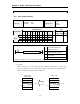
PUT, PUTP
FUN(234) PUT
FUN(235) PUTP
Applicable CPU
K200S
K300S
K1000S
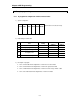
Available devices Flag
Instructions
M P K L F T C S D #D Integer
Steps
Error
(F110)
Zero
(F111)
Carry
(F112)
n1 ¡
S ¡
D ¡ ¡ ¡ ¡* ¡ ¡ ¡ ¡
PUT
PUTP
n2 ¡
9
¡
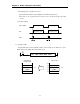
Operand setting
n1
Slot number at which A/D
module is mounted
D
Start address of buffer memory
at which data will be written
D
Start address of source data of
CPU module
n2 Number of word to be written
* Available only when do not use computer link module or data link module
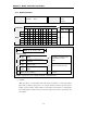
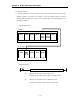
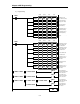
1) Functions
Write the data of ‘n2’ words, which start at the address specified as ‘S’ of CPU, and
transfer the data into the block starting at the address specified as ‘D’ of buffer memory
inside the A/D module mounted at the slot number ‘n1’.
Buffer memory
of A/D module
CPU module
[ D ]
[ S ]
[ D+n2-1 ]
‘n2’ words
[ S+n2-1 ]
‘n2’ words
PUT(P) n1 D S n2
Input
condition