MC-12 Digital Controller User Guide
IMPORTANT SAFETY INSTRUCTIONS 1. Read these instructions. 2. Keep these instructions. 3. Heed all warnings. 4. Follow all instructions. 5. Do not use this apparatus near water. 6. Clean only with a dry cloth. 7. Do not block any ventilation openings. Install in accordance with the manufacturer’s instructions. 8. Do not install near any heat sources such as radiators, heat registers, stoves, or another apparatus (including amplifiers) that produces heat. 9.
Manufactured under license from Dolby Laboratories. "Dolby," "Pro Logic," "Surround EX," and the double-D symbol are trademarks of Dolby Laboratories. Manufactured under license from THX Ltd. U.S. patent numbers 5,043,970; 5,189,703; and/or 5,222,059. European patent number 0323830. Other U.S. and foreign patents pending. Ultra2 and THX are trademarks or registered trademarks of THX Ltd. Surround EX is a trademark of Dolby Laboratories. Used under authorization. Lexicon, Inc.
Introduction Lexicon DOCUMENTATION CONVENTIONS This document contains general safety, installation, and operation instructions for the MC-12 and MC-12 Balanced Digital Controllers. It is important to read this user guide before attempting to use this product. Pay particular attention to safety instructions.
Introduction MC-12 US Important Safety Instructions . . . . . . . . . . . . . . . . . . . v Section 1: Getting Started DE Wichtige Sicherheitshinweise . . . . . . . . . . . . . . . . . . . . v About the MC-12 . . . . . . . . . . . . . . . . . . . . . . . . . . . . . . . . . 1-2 ES Instrucciones de seguridad importantes . . . . . . . . . . . . vi FR Instructions importantes relatives à la sécurité . . . . . . . . vi IT Importanti norme di sicurezza . . . . . . . . . . . . . . . . . . .
Introduction Lexicon Section 3: SETUP Section 5: MODE ADJUST SETUP . . . . . . . . . . . . . . . . . . . . . . . . . . . . . . . . . . . . . . . . . 3-2 Listening Mode Descriptions . . . . . . . . . . . . . . . . . . . . . . . . . 5-5 INPUT SETUP . . . . . . . . . . . . . . . . . . . . . . . . . . . . . . . . . . . .
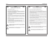
Introduction MC-12 US ENGLISH US DE IMPORTANT SAFETY INSTRUCTIONS DEUTSCH DE WICHTIGE SICHERHEITSHINWEISE • Save these instructions for later use. • Bewahren Sie diese Anleitungen zur späteren Benutzung auf. • Follow all instructions and warnings marked on the unit. • Befolgen Sie alle Anleitungen und alle Warnhinweise auf dem Gerät • Always use with the correct line voltage. Refer to the manufacturer’s operating instructions for power requirements.
Introduction ES Lexicon ESPAÑOL ES FR INSTRUCCIONES DE SEGURIDAD IMPORTANTES • Guarde estas instrucciones para futuras referencias. • Siga todas las instrucciones y tenga en cuenta las advertencias que aparecen en la unidad y en las instrucciones de funcionamiento. • Utilice siempre la tensión de línea correcta. Consulte las instrucciones del fabricante, donde se especifican los requisitos de alimentación.
Introduction MC-12 IT ITALIANO IT PT IMPORTANTI NORME DI SICUREZZA PORTUGUESE PT INSTRUÇÕES IMPORTANTES DE SEGURANÇA • Conservare le presenti norme per l’utilizzo futuro. • Guarde essas instruções para uso posterior. • Seguire sempre tutte le istruzioni e gli avvertimenti segnati sull’unità e nelle istruzioni operative. • Siga todas as instruções e fique atento aos avisos marcados na unidade e nas instruções de operação. • Utilizzare sempre la corretta tensione di alimentazione.
Introduction DK Lexicon DANSK DK FI VIGTIG INFORMATION OM SIKKERHED SUOMI FI TÄRKEITÄ TURVALLISUUSOHJEITA • Gem denne vejledning til senere brug. • Säilytä nämä ohjeet tulevaa käyttöä varten. • Følg alle anvisninger og advarsler på apparatet. • Seuraa kaikkia yksikköön merkittyjä ohjeita ja varoituksia. • Apparatet skal altid tilsluttes den korrekte spænding. Der henvises til brugsanvisningen, der indeholder specifikationer for strømforsyning.
Introduction MC-12 NO NORSK NO SE VIKTIG INFORMASJON OM SIKKERHET SVENSKA SE VIKTIGA SÄKERHETSFÖRESKRIFTER • Ta vare på denne veiledningen for senere bruk. • Spara dessa föreskrifter för framtida bruk. • Følg alle anvisningene og advarslene som er angitt på apparatet. • Följ alla anvisningar och varningar som anges på enheten. • Apparatet skal alltid anvendes med korrekt spenning. Produktbeskrivelsen inneholder spesifikasjoner for strømkrav.
Introduction US Unpacking and Inspection After unpacking the unit, save all packing materials in case the unit ever needs to be shipped. Thoroughly inspect the modules and packing materials for signs of damage. Report any damage to the carrier at once; report equipment malfunction to the dealer. DE Desembalaje e inspección Después de desembalar la unidad, guarde todos los materiales de embalaje por si alguna vez transportar la unidad.
1 Getting Started About the MC-12 . . . . . . . . . . . . . . . . . . . . . . . . . . . . . . . . . . . . 1-2 Highlights • Product Registration Installation Considerations . . . . . . . . . . . . . . . . . . . . . . . . . . . . . . 1-4 Do • Do Not Remote Control Battery Installation . . . . . . . . . . . . . . . . . . . . . . .
Getting Started ABOUT THE MC-12 Thank you for purchasing the MC-12 Digital Controller, a referencequality, 12-channel audio and video control center with independent zone monitoring to provide control of input source selection in three zones at the same time. As flexible as it is powerful, the MC-12 includes 12 configurable inputs, each of which can be assigned to its 13 digital audio, 8 analog audio, 5 composite video, 8 S-video, or 4 component video input connectors.
Getting Started MC-12 Complementing its pristine audio performance, the MC-12 includes two broadcast-quality video switchers. An ultra-wide bandwidth component video switcher accepts analog component or RGB video signals, while a composite and S-video switcher accepts high-quality NTSC, PAL, or SECAM video signals. The component video switcher can pass High-Definition TV (HDTV) and Standard-Definition TV signals. Both switchers are designed to pass video signals without alteration or degradation.
Getting Started Lexicon PRODUCT REGISTRATION DO NOT Please register the MC-12 Digital Controller within 15 days of purchase. To do so, register online at www.lexicon.com or complete and return the product registration card attached to the back cover of this user guide. The product registration card serves no warranty purposes. Retain the sales receipt as proof of warranty coverage. • Place the MC-12 on a thick rug or carpet or cover the MC-12 with a cloth, as this might prevent proper cooling.
Getting Started MC-12 REMOTE CONTROL BATTERY INSTALLATION The remote control requires two AA batteries that should be replaced as needed. It is recommended to use Alkaline batteries, which last longer without leaking. When the batteries are low on power, the remote control enters a low-voltage condition that prevents it from operating the MC-12. When this occurs, follow the instructions below to replace the batteries. Normal operation will resume when new batteries are installed.
2 Basic Operation Front Panel Overview . . . . . . . . . . . . . . . . . . . . . . . . . . . . . . . . . 2-2 Rear Panel Overview . . . . . . . . . . . . . . . . . . . . . . . . . . . . . . . . . . 2-6 Remote Control Overview . . . . . . . . . . . . . . . . . . . . . . . . . . . . . 2-10 Operation Considerations • MAIN MENU • Menu Navigation • Menu Item Selection • Command Bank Activation • Command Matrix Understanding the Zones . . . . . . . . . . . . . . . . . . . . . . . . . . . . .
Basic Operation Lexicon FRONT PANEL OVERVIEW 2 3 1 6 4 5 7 9 8 11 10 12 The MC-12 front panel is shown above. The MC-12 Balanced front panel is shown on page 2-4. The front panels are identical, except the MC-12 Balanced has a larger chassis. The numbers in the front panel illustrations above and on page 2-4 correspond with the numbered items on pages 2-2, 2-3, 2-4, and 2-5. 1. Standby Button Activates and deactivates standby mode when the MC-12 is powered on with the rear panel power switch.
Basic Operation MC-12 Note: Power is still supplied to the MC-12 when standby mode is activated. For example, if a 2-channel source is present, the Mode and buttons scroll through available 2-channel listening modes. The selected listening mode appears in the bottom-left corner of the Main Zone two-line status. The MC-12 automatically activates the selected listening mode when scrolling stops. 2. Front Panel Display Indicates the current input, listening mode, input source, and volume level.
Basic Operation Lexicon Front Panel Overview (continued from page 2-3) 2 3 1 6 4 5 7 9 8 11 10 12 The MC-12 Balanced front panel is shown above. The MC-12 front panel is shown on page 2-2. The front panels are identical, except the MC-12 Balanced has a larger chassis. The numbers in the front panel illustrations above and on page 2-2 correspond with the numbered items on pages 2-2, 2-3, 2-4, and 2-5. To use the volume knob to adjust Main Zone volume level: 1.
Basic Operation MC-12 To use the volume knob to adjust Zone 2 or Record Zone volume level: 1. Press and hold the front panel Zone 2 or Record Zone input selection button that corresponds with the current input source. For instance, if the current input source is using the DVD1 input, press and hold the DVD1 input selection button. 2.
Basic Operation Lexicon REAR PANEL OVERVIEW 9 9 1 2 3 INPUTS 4 INPUT 1 5 VIDEO Y PR COMPONENT VIDEO INPUT 2 PB Y PR PR PB 10 Y PB PR Y 11 2 3 4 5 7 6 2 1 L (L) L (C) (LS) CENTER AUDIO (R) R (SUB) L L (RS) Fix AUX L R R VIDEO ZONE 2 Var Fix Var CAUTION RISK OF ELECTRIC SHOCK DO NOT OPEN L L 2 MICROPHONE INPUTS 2 3 3 1 2 5 AUDIO AC 100-240V~, 50-60 Hz, 90W 1 RS 232 2 IR IN 6 6 + – PWR CAUTION AUDIO RISQUE DE CHOC ELECTRIQUE NE PAS OUVRI
Basic Operation MC-12 1. Power Switch Connects power to the AC input connector and disconnects power from the AC input connector. The c represents the "off" position and the|represents the "on" position. When the MC-12 is powered on, the standby button can be used to activate and deactivate standby mode. When the MC-12 is powered off, standby mode is not available. 2. AC Input Connector Provides power to the MC-12 through the supplied power cord (3 wire, 10 amp, IEC 320). column. When a 5.
Basic Operation Lexicon Rear Panel Overview (continued from page 2-7) 9 9 1 2 3 INPUTS 4 INPUT 1 5 VIDEO Y PR COMPONENT VIDEO INPUT 2 PB Y PR PR PB 10 Y PB PR Y 11 2 3 4 5 7 6 2 1 L L R R (L) (C) (LS) (R) (SUB) (RS) CENTER SIDE SUBWOOFER 2 Y 8 FRONT SERIAL NO. LEXICON, INC. DESIGNED AND ASSEMBLED IN U.S.A.
Basic Operation MC-12 7. Record Zone Audio Output Connectors Provide analog and digital audio output in the Record Zone. Two stereo connectors labeled Audio L/R are available for analog audio output. The connector labeled Fix passes audio at fixed output levels. The connector labeled Var passes audio at variable output levels and includes a built-in volume control. Two S/PDIF connectors (one coaxial and one optical) are available for digital audio output. 10.
Basic Operation Rear Panel Overview (continued from page 2-9) Note: The numbered items below correspond with the rear panel illustrations on pages 2-6 and 2-8. 13.Trigger Output Connectors Provide 12V DC output to control connected components. Three trigger output connectors are available on a removable terminal block. The connector labeled PWR – the power trigger output connector – is not configurable. It is activated when the MC-12 is activated, and deactivated when the MC-12 is deactivated.
Basic Operation MC-12 MENU NAVIGATION MAIN MENU The MAIN MENU represents the beginning of the menu structure. It can be used to open the three main menu branches: MODE ADJUST, AUDIO CONTROLS, and SETUP. Button M EN U MAIN MENU MODE ADJUST AUDIO CONTROLS SETUP The remote control MENU and arrow buttons must be used to navigate the extensive menu structure shown in the Appendix. The table below indicates the navigation commands remote control buttons perform when the Main Zone command bank is activated.
Basic Operation Lexicon MENU ITEM SELECTION The remote control arrow buttons must be used to select menu items. MAIN MENU MODE ADJUST AUDIO CONTROLS SETUP SETUP INPUTS SPEAKERS REAR PANEL CONFIG DISPLAYS VOLUME CONTROLS TRIGGERS LOCK OPTIONS DISPLAY SETUP ON-SCREEN DISPLAY FRONT PANEL DISPLAY A/V SYNC DELAY OFF CUSTOM NAME OFF OFF EDIT CUSTOM NAME ON OFF To select a menu item on the open menu: 1. Press the and arrow buttons to highlight the desired menu item. 2.
Basic Operation MC-12 To select a parameter setting with a horizontal graph: To activate a command bank: 1. When the horizontal graph appears, press the and arrow buttons to increase and decrease the setting in designated increments. The current setting appears at the right of the parameter name on the on-screen and front panel displays. 1. Press and release a command bank selection button to activate the desired command bank. 2.
Basic Operation Lexicon 2 1 LIGHT MAIN ZONE Button 3 SHIFT DVD-1 DVD-2 LD TV SAT VCR CD PVR GAME TAPE TUNER AUX FP MODE BLUE Zone 2 Record Zone Shift Activates and deactivates standby mode when the MC-12 is powered on with the rear panel power switch. The standby button performs no function when the MC-12 is powered off with the rear panel power switch.
Basic Operation MC-12 Button LIGHT MAIN ZONE 4 REC Main Zone Zone 2 Record Zone SA T Selects the SAT input for the Main Zone. Selects the SAT input for Zone 2. Selects the SAT input for the Record Zone. Sets the AUDIO CONTROLS menu LOUDNESS parameter to OFF. VC R Selects the VCR input for the Main Zone. Selects the VCR input for Zone 2. Selects the VCR input for the Record Zone. Reserved for future expansion. CD Selects the CD input for the Main Zone. Selects the CD input for Zone 2.
Basic Operation Lexicon Button LIGHT MAIN ZONE REC 5 FP 6 BLUE 7 O SD SHIFT DVD-1 DVD-2 LD TV SAT VCR CD PVR GAME TAPE TUNER AUX 5 6 FP 8 MODE BLUE VOL 9 OSD 7 STAT 8 MODE MENU 2 CH MUSIC 9 VOL 10 2-16 Zone 2 Record Zone Shift Toggles the FRONT PANEL DISPLAY menu STATUS parameter between ALWAYS OFF and its current setting. Sets Zone 2 volume level to -15dB. Sets Record Zone volume level to -15dB. Sets Main Zone volume level to -15dB.
Basic Operation MC-12 Button LIGHT MAIN ZONE REC 11 STAT 12 M EN U Main Zone Zone 2 Record Zone Shift Displays the Main Zone two-line status for 2 seconds. Displays the Zone 2 two-line status for 2 seconds. Displays the Record Zone two-line status for 2 seconds. Opens and closes the status menu for the current input source. When a menu is open, pressing the MENU button closes the menu structure. When no menus are open, pressing the MENU button opens the MAIN MENU.
Basic Operation Lexicon Button LIGHT MAIN ZONE 16 REC Main Zone Zone 2 Record Zone Selects the THX mode family for the current input source. Reserved for future expansion. Reserved for future expansion. Activates the 5.1 ULTRA2, 5.1 SurEX, or 5.1 listening mode when a 5.1-channel Dolby Digital source is present. Selects the Dolby mode family for the current input source. Reserved for future expansion. Reserved for future expansion.
Basic Operation MC-12 UNDERSTANDING THE ZONES The MC-12 features three zones of operation, called the Main Zone, Zone 2, and the Record Zone. The Main Zone controls audio and video sources in the primary listening space. Zone 2 controls audio and video sources in the secondary listening space. And, the Record Zone controls audio and video sources sent to recording devices or to a third listening space.
Basic Operation Two-Line Status (continued from page 2-19) Record Zone Two-Line Status Opens on the on-screen and front panel DVD1 %!D VOL RECORD -34dB displays whenever the MC-12 detects a Record Zone status change. The Record Zone two-line status indicates the current input, input source, and volume level selected in the Record Zone. The ON-SCREEN DISPLAY menu STATUS parameter can be used to control the length of time for which the two-line status appears on the on-screen and front panel displays.
Basic Operation MC-12 2CH STATUS INPUT MODE INPUT TYPE SAMPLE RATE dB L 0 -6 -15 -30 C X R X D STATUS INPUT MODE CHANNELS BIT RATE EX ENCODED SL SR SB LFE X X X X X dB 0 -6 -15 -30 L C X R X PG1 SL SR SB LFE X X X X -45 -45 5.1 ANALOG STATUS INPUT MODE INPUT TYPE SAMPLE RATE 5.1a BYPASS STATUS INPUT MODE INPUT TYPE dB 0 -6 -15 -30 L C X R X D STATUS SAMPLE RATE 2.
Basic Operation Lexicon D STATUS STATUS •Provides information about Dolby Digital sources. • Provides information about dts(-ES) sources. • Includes L, C, R, SL, SR, and LFE level meters. • Includes L, C, R, SL, SR, SB, and LFE level meters. Parameter Possible Settings Parameter Possible Settings INPUT The current input INPUT The current input MODE The current listening mode MODE The current listening mode CHANNELS 3/2.1, 3/2, 3/1, 2/2, 2/1, 2/0, 1/0 CHANNELS 3/3.1, 3/2.
Basic Operation MC-12 5.1 ANALOG STATUS • Provides information about 5.1-channel analog sources. • Includes L, C, R, SL, SR, and LFE level meters. 2CH BYPASS STATUS • Provides information about 2-channel analog sources when the MAIN ADV menu ANALOG BYPASS parameter is set to ON. Parameter Possible Settings Parameter Possible Settings INPUT The current input INPUT The current input MODE The current listening mode MODE 2CH BYPASS INPUT TYPE ANLG INPUT TYPE BYPASS SAMPLE RATE 44.
Basic Operation Lexicon STATUS MENU PARAMETER DESCRIPTIONS 2.0 ENCODING MATRIX, NONE Indicates whether or not a matrix-encoded source is detected. When the parameter setting is MATRIX, a matrix-encoded source is detected. When the parameter setting is NONE, a matrix-encoded source is not detected. The MC-12 cannot automatically detect matrix encoding in non-flagged input sources. BIT RATE 32 to 640 kbps or 754 to 1509.7kbps Indicates the rate at which the input signal is encoded.
Basic Operation MC-12 INPUT WORD LENGTH Indicates the current input (i.e. DVD1). Indicates the word length of the audio data present in the input signal. INPUT TYPE ANLG, BYP, PCM, --- Indicates the input source that is present. When the parameter setting is ANLG, an analog audio source is present and the MAIN ADV menu ANALOG BYPASS parameter is set to OFF. When the parameter setting is BYP, an analog audio source is present and the ANALOG BYPASS parameter is set to ON.
3 SETUP SETUP . . . . . . . . . . . . . . . . . . . . . . . . . . . . . . . . . . . . . . . . . . . . 3-2 INPUT SETUP . . . . . . . . . . . . . . . . . . . . . . . . . . . . . . . . . . . . . . . 3-3 Changing Input Names • Assigning Audio & Video Input Connectors • Selecting Preferred Listening Modes • Configuring Advanced Input Settings SPEAKER SETUP. . . . . . . . . . . . . . . . . . . . . . . . . . . . . . . . . . . . .
SETUP Lexicon REAR PANEL CONFIG SETUP Selecting the MAIN MENU SETUP option opens the SETUP menu shown below, which can be used to configure the MC-12. MAIN MENU MODE ADJUST AUDIO CONTROLS SETUP SETUP INPUTS SPEAKERS REAR PANEL CONFIG DISPLAYS VOLUME CONTROLS TRIGGERS LOCK OPTIONS INPUTS SETUP INPUTS Prompts the selection of the desired input (i.e. DVD1).
SETUP MC-12 LOCK OPTIONS SETUP LOCK OPTIONS Opens the LOCK OPTIONS menu, which can be used to protect MODE ADJUST, AUDIO CONTROLS, and SETUP menu branch parameter settings from accidental changes. Refer to page 3-66 for more information. INPUT SETUP SETUP INPUTS DVD1 DVD1 INPUT SETUP Selecting the SETUP menu INPUTS option prompts the selection of the desired input (i.e. DVD1).
SETUP Lexicon CHANGING INPUT NAMES SETUP INPUTS DVD1 NAME Selecting the INPUT SETUP menu NAME option opens the INPUT NAME menu shown below, which can be used to customize or restore the factory-default name of the selected input. Factory-default input names correspond to front panel and remote control input selection button labels.
SETUP MC-12 • Press the arrow button to return to the previous character space. When the cursor is positioned in the first character space, pressing the arrow button will close the EDIT INPUT NAME drop-down menu. 4. When the desired input name has been entered, press the arrow button until the EDIT INPUT NAME drop-down menu closes. RESTORE DEFAULT NAME SETUP INPUTS DVD1 NAME RESTORE DEFAULT NAME Restores the factory-default name of the selected input.
SETUP Lexicon ASSIGNING AUDIO & VIDEO INPUT CONNECTORS The MC-12 has 12 configurable inputs, each of which can be assigned to its 13 digital audio, 8 analog audio, 5 composite video, 8 S-video, or 4 component video input connectors.
SETUP MC-12 When no digital audio input connector is assigned, the MC-12 automatically sets the: • MAIN ADV menu INPUT SELECT parameter to ANALOG • INPUT SETUP menu ZONE2 IN parameter to ANLG • INPUT SETUP menu RECORD IN parameter to ANLG ANALOG IN SETUP INPUTS ANALOG-1 to 8, 5.1 ANLG (6-8), NONE DVD1 The configuration of the analog audio input connectors determines available ANALOG IN parameter settings.
SETUP Lexicon Assigning Audio & Video Input Connectors (continued from page 3-7) MAIN MENU MODE ADJUST AUDIO CONTROLS SETUP SETUP INPUTS SPEAKERS REAR PANEL CONFIG DISPLAYS VOLUME CONTROLS TRIGGERS LOCK OPTIONS INPUT SETUP DVD1 DVD2 LD TV SAT VCR CD PVR GAME TAPE TUNER AUX DVD1 INPUT SETUP NAME DVD1 DIGITAL IN COAX-1 ANALOG IN NONE ANLG IN LVL AUTO VIDEO IN S-VIDEO-1 COMPONENT IN 1 2-CH FILM D 5.1 FILM FILM 5.1a 5.
SETUP MC-12 AUTO SETUP ON, OFF INPUTS DVD1 ANLG IN LVL AUTO AUTO GAIN SETUP Activates automatic adjustment of 2-channel analog audio input levels. When ON is selected, the MC-12 automatically monitors and optimizes 2-channel analog audio input levels. When the input signal is too high, the MC-12 quickly decreases input levels to avoid overload. When the input signal is too low, the MC-12 slowly increases input levels to maximize signal-to-noise ratio and dynamic range.
SETUP Lexicon Assigning Audio & Video Input Connectors VIDEO IN SETUP (continued from page 3-9) COMPOSITE-1 to 5, S-VIDEO-1 to 8, NONE INPUTS DVD1 VIDEO IN COMPONENT IN SETUP Opens the VIDEO IN menu shown below, which can be used to assign a composite or S-video input connector for the selected input. INPUTS Note: • Composite video output connectors are available when a composite or S-video source is present. • • S-video output connectors are available when an S-video source is present.
SETUP MC-12 MAIN MENU MODE ADJUST AUDIO CONTROLS SETUP SETUP INPUTS SPEAKERS REAR PANEL CONFIG DISPLAYS VOLUME CONTROLS TRIGGERS LOCK OPTIONS INPUT SETUP DVD1 DVD2 LD TV SAT VCR CD PVR GAME TAPE TUNER AUX DVD1 INPUT SETUP NAME DVD1 DIGITAL IN COAX-1 ANALOG IN NONE ANLG IN LVL AUTO VIDEO IN S-VIDEO-1 COMPONENT IN 1 2-CH FILM D 5.1 FILM FILM 5.1a 5.
SETUP Lexicon Selecting Preferred Listening Modes MAIN MENU MODE ADJUST AUDIO CONTROLS SETUP DVD1 SETUP INPUTS SPEAKERS REAR PANEL CONFIG DISPLAYS VOLUME CONTROLS TRIGGERS LOCK OPTIONS MODE FILM MUSIC 2-CHAN USE LAST (continued from page 3-11) INPUT SETUP DVD1 DVD2 LD TV SAT VCR CD PVR GAME TAPE TUNER AUX DVD1 INPUT SETUP NAME DVD1 DIGITAL IN COAX-1 ANALOG IN NONE ANLG IN LVL AUTO VIDEO IN S-VIDEO-1 COMPONENT IN 1 2-CH FILM D 5.1 FILM FILM 5.1a 5.
SETUP MC-12 was activated the last time a 2-channel source was present. The MC-12 will not activate a listening mode unless a 44.1 or 48kHz PCM digital source is present. The listening modes are not compatible with 88.2 or 96kHz, Dolby Digital, or analog sources. R R Note: When the 2-CH parameter is set to USE LAST, the MC-12 will not activate the 2-CHANNEL listening mode if the 2CH button was used to activate the 2-CHANNEL listening mode the last time a 2-channel source was present.
SETUP Lexicon CONFIGURING ADVANCED INPUT SETTINGS MAIN MENU MODE ADJUST AUDIO CONTROLS SETUP SETUP INPUTS SPEAKERS REAR PANEL CONFIG DISPLAYS VOLUME CONTROLS TRIGGERS LOCK OPTIONS INPUT SETUP DVD1 DVD2 LD TV SAT VCR CD PVR GAME TAPE TUNER AUX DVD1 INPUT SETUP NAME DVD1 DIGITAL IN COAX-1 ANALOG IN NONE ANLG IN LVL AUTO VIDEO IN S-VIDEO-1 COMPONENT IN 1 2-CH FILM D 5.1 FILM FILM 5.1a 5.
SETUP MC-12 Parameter Possible Settings INPUT SELECT DIGITAL, ANALOG, AUTO ANALOG BYPASS ON, OFF S-VIDEO 16:9 AUTO, OFF S-VIDEO OSD 4:3 ON, OFF COMPONENT OSD ON, OFF INPUT SELECT SETUP INPUTS • When a 5.1-channel analog source is present, the MC-12 passes analog input signals to the Main Zone audio output connectors as indicated in the table on pages 2-7 and 3-58.
SETUP Lexicon Configuring Advanced Input Settings (continued from page 3-15) INPUT SELECT Parameter Settings DIGITAL ANALOG AUTO The MC-12 sends the assigned digital audio input connector to the Main Zone audio output connectors. The MC-12 ignores the assigned analog audio input connector. The MC-12 sends the assigned analog audio input connector to the Main Zone audio output connectors. The MC-12 ignores the assigned digital audio input connector.
SETUP MC-12 S-VIDEO OSD 4:3 SETUP INPUTS DVD1 ON, OFF MAIN ADVANCED S-VIDEO OSD 4:3 Controls the on-screen display aspect ratio when the display device is connected to a Main Zone S-video output connector. Aspect ratio refers to the size of the picture or the display device screen. A 4:3 aspect ratio is almost square. A 16:9 aspect ratio, often referred to as widescreen, is almost twice as wide as high.
SETUP Lexicon Configuring Advanced Input Settings (continued from page 3-17) ZONE2 & RECORD IN Parameter Settings DIGITAL ANLG (Analog) DMIX (Downmix) The MC-12 sends the assigned digital audio input connector to the Zone 2 or Record Zone audio output connectors. The MC-12 ignores the assigned analog audio input connector. Independent zone monitoring is available. The MC-12 sends the assigned analog audio input connector to the Zone 2 or Record Zone audio output connectors.
SETUP MC-12 MAIN MENU MODE ADJUST AUDIO CONTROLS SETUP SETUP INPUTS SPEAKERS REAR PANEL CONFIG DISPLAYS VOLUME CONTROLS TRIGGERS LOCK OPTIONS INPUT SETUP DVD1 DVD2 LD TV SAT VCR CD PVR GAME TAPE TUNER AUX DVD1 INPUT SETUP NAME DVD1 DIGITAL IN COAX-1 ANALOG IN NONE ANLG IN LVL AUTO VIDEO IN S-VIDEO-1 COMPONENT IN 1 2-CH FILM D 5.1 FILM FILM 5.1a 5.1a FILM MAIN ADVANCED ZONE2 IN DIGITAL RECORD IN DIGITAL RECORD ADVANCED -18 to +12dB DVD1 RECORD ADV ANLG IN LVL +0dB DIGITAL BYPASS OFF DIG OUT RATE 44.
SETUP Lexicon Configuring Advanced Input Settings (continued from page 3-19) DIG OUT RATE SETUP ANLG IN LVL SETUP INPUTS -18 to +12dB DVD1 RECORD ADVANCED ANLG IN LVL Allows adjustment of analog audio input levels for input signals sent to the Record Zone digital audio output connectors. The MC-12 applies these adjustments to input signals before passing them to the Record Zone digital audio output connectors.
SETUP MC-12 SPEAKER SETUP SETUP Note: SPEAKERS Selecting the SETUP menu SPEAKERS option opens the SPEAKER SETUP menu shown below, which can be used to configure the Main Zone audio output connectors for the desired speaker setup. The Main Zone includes 10 unbalanced audio output connectors labeled Front L/R, Center, LFE, Subwoofer L/R, Side L/R, and Rear L/R. Two additional audio output connectors labeled Aux L/R are provided for future expansion.
SETUP Lexicon Setting Crossover Points (continued from page 3-21) MAIN MENU MODE ADJUST AUDIO CONTROLS SETUP SETUP INPUTS SPEAKERS REAR PANEL CONFIG DISPLAYS VOLUME CONTROLS TRIGGERS LOCK OPTIONS SPEAKER SETUP SET CROSSOVERS CHECK MICROPHONES AUTOMATIC MANUAL CROSSOVER SETUP CUSTOM SETUP THX SETUP R SET CROSSOVERS BEFORE CALIBRATING 40Hz SR RR 60Hz 60Hz C 60Hz M SUB 40Hz Custom Speaker Setups SETUP SPEAKERS SET CROSSOVERS • CUSTOM SETUP Selecting the CROSSOVER SETUP menu CUSTOM SETUP optio
SETUP MC-12 Highpass Filter Lowpass Filter dB 0 0 -12 -24 -36 -48 0 0 -60 10 Highpass filters attenuate low-frequency signals at 24dB per octave. The curves in the graph above indicate the frequency response of each crossover point. From left to right, the curves represent crossover points from 30 to 120Hz. This graph does not include the THX 80Hz crossover point, which attenuates low-frequency signals at 12dB per octave.
SETUP Lexicon Setting Crossover Points (continued from page 3-23) MAIN MENU MODE ADJUST AUDIO CONTROLS SETUP SETUP INPUTS SPEAKERS REAR PANEL CONFIG DISPLAYS VOLUME CONTROLS TRIGGERS LOCK OPTIONS SPEAKER SETUP SET CROSSOVERS CHECK MICROPHONES AUTOMATIC MANUAL CROSSOVER SETUP CUSTOM SETUP THX SETUP R SET CROSSOVERS BEFORE CALIBRATING 40Hz SR RR 60Hz 60Hz C 60Hz M SUB 40Hz THX Speaker Setups SETUP SPEAKERS SET CROSSOVERS THX SETUP Selecting the CROSSOVER SETUP menu THX SETUP option opens the
SETUP MC-12 Speaker Setup Parameters SETUP SPEAKERS SET CROSSOVERS OR SETUP CUSTOM SETUP SPEAKERS The table below indicates the speaker setup parameters that can be used to configure the Main Zone audio output connectors for the desired speaker setup. These parameters are available on the CUSTOM and THX SETUP menus. SET CROSSOVERS THX SETUP Speaker setup parameters perform the same function regardless of which speaker setup is selected.
SETUP Lexicon Setting Crossover Points (continued from page 3-25) MAIN MENU MODE ADJUST AUDIO CONTROLS SETUP SETUP INPUTS SPEAKERS REAR PANEL CONFIG DISPLAYS VOLUME CONTROLS TRIGGERS LOCK OPTIONS SPEAKER SETUP SET CROSSOVERS CHECK MICROPHONES AUTOMATIC MANUAL CROSSOVER SETUP CUSTOM SETUP THX SETUP R SET CROSSOVERS BEFORE CALIBRATING 40Hz SR RR 60Hz 60Hz C 60Hz M SUB 40Hz SUB XOVER FULL 30Hz 40Hz 50Hz 60Hz 70Hz 80Hz THX 80Hz 90Hz 100Hz 110Hz 120Hz FRONT L/R SUBWOOFERS L/R MONO STEREO NONE RE
SETUP MC-12 SETUP SPEAKERS SET CROSSOVERS SIDE L/R THX SETUP When a THX speaker setup is selected, the FRONT L/R parameter cannot be adjusted. The MC-12 automatically applies a THX 80Hz crossover point to the Front L/R output connectors. Assigns a crossover point for the Main Zone audio output connectors labeled Side L/R. SETUP CENTER FULL, 30 to 120Hz, THX 80Hz, NONE Assigns a crossover point for the Main Zone audio output connector labeled Center.
SETUP Lexicon Setting Crossover Points (continued from page 3-27) MAIN MENU MODE ADJUST AUDIO CONTROLS SETUP SETUP INPUTS SPEAKERS REAR PANEL CONFIG DISPLAYS VOLUME CONTROLS TRIGGERS LOCK OPTIONS SPEAKER SETUP SET CROSSOVERS CHECK MICROPHONES AUTOMATIC MANUAL CROSSOVER SETUP CUSTOM SETUP THX SETUP R SET CROSSOVERS BEFORE CALIBRATING 40Hz SR RR 60Hz 60Hz THX SPEAKER SETUP !CAUTION! PRESSING THE V BUTTON WILL AUTOMATICALLY CHANGE THE OUTPUTS TO A THX SPEAKER CONFIGURATION C 60Hz M SUB 40Hz L 40
SETUP MC-12 SUB L/R SETUP SPEAKERS MONO, STEREO, NONE SET CROSSOVERS CUSTOM SETUP SUB L/R Configures the Main Zone audio output connector labeled Subwoofer L/R for a speaker setup that includes one, two, or no subwoofer(s). When a custom speaker setup is selected, the SUB L/R parameter opens the SUBWOOFERS L/R menu shown on page 3-26, which can be used to select the desired configuration for the Subwoofer L/R output connectors. • Select MONO if the speaker setup includes one subwoofer.
SETUP Lexicon Setting Crossover Points (continued from page 3-29) MAIN MENU MODE ADJUST AUDIO CONTROLS SETUP SETUP INPUTS SPEAKERS REAR PANEL CONFIG DISPLAYS VOLUME CONTROLS TRIGGERS LOCK OPTIONS SPEAKER SETUP SET CROSSOVERS CHECK MICROPHONES AUTOMATIC MANUAL CROSSOVER SETUP CUSTOM SETUP THX SETUP R SET CROSSOVERS BEFORE CALIBRATING 40Hz SR RR 60Hz 60Hz C 60Hz M SUB 40Hz THX SPEAKER SETUP !CAUTION! PRESSING THE V BUTTON WILL AUTOMATICALLY CHANGE THE OUTPUTS TO A THX SPEAKER CONFIGURATION ON,
SETUP MC-12 ULTRA2 SUB SETUP SPEAKERS OR SETUP SPEAKERS ON, OFF SET CROSSOVERS SET CROSSOVERS CUSTOM SETUP THX SETUP @** ULTRA2 SUB @** ULTRA2 SUB Select ON if the subwoofer using the Main Zone audio output connectors labeled Subwoofer L/R is THX Ultra2-certified. When ON is selected, the BGC parameter can be used to adjust boundary gain compensation. Select OFF if the subwoofer using the Main Zone audio output connectors labeled Subwoofer L/R is not THX Ultra2-certified.
SETUP Lexicon ASA (Advanced Speaker Array) (continued from page 3-31) When the 7/5 button is used to toggle between 7- and 5-channel playback, the MC-12 automatically: • Activates ASA processing during 7-channel playback. • Deactivates ASA processing during 5-channel playback. • Switches between the 5.1 ULTRA2 and 5.1 , ULTRA2 and , or 5.1a ULTRA2 and 5.1a listening modes.
MC-12 SETUP UNITS FEET, METERS SETUP SPEAKERS MANUAL SPEAKER DISTANCES UNITS Determines the unit of measurement in which speaker distances are calculated on ALL speaker distance menus. When FEET is selected, the MC-12 calculates speaker distances in feet. When METERS is selected, the MC-12 calculates speaker distances in meters. When the UNITS parameter setting is adjusted, the MC-12 automatically adjusts speaker distances to the closest available value in the selected unit of measurement.
SETUP Lexicon AUTOMATIC CALIBRATION The MC-12 offers automatic calibration of speaker distances, output levels, or both. The table below indicates available automatic calibration options. A successful microphone check is required before automatic calibration can be performed. Automatic Options Details MICROPHONE CHECK • Confirms that the microphones are properly connected and functioning.
SETUP MC-12 Step A: Connecting the Microphones CAUTION • The microphones included in the Lexicon Microphone Kit require careful handling. Dropping or otherwise physically abusing the microphones might cause errors during use or irreparable damage to the microphone. • Never make or break microphone input connections unless the MC-12 is powered off with the rear panel power switch OR standby mode is activated with the front panel or remote control standby button.
SETUP Lexicon Step B: Positioning the Microphones for the Microphone Check B-1. Refer to the microphone placement examples that begin below to position the microphones for the microphone check.
SETUP MC-12 RECOMMENDED microphone positioning for the microphone check During the microphone check, do not: ✗ separate the microphones ✗ scatter the microphones throughout the listening space ✗ obstruct the line-of-sight path between the microphones and the speakers ✗ position the microphones on the floor, on seat cushions, or in locations obstructed by furniture and other fixtures, where echoes might obscure calibration noise signals ✗ position the microphones within 2 feet (0.
SETUP Lexicon Step C: Checking the Microphones MAIN MENU MODE ADJUST AUDIO CONTROLS SETUP SETUP INPUTS SPEAKERS REAR PANEL CONFIG DISPLAYS VOLUME CONTROLS TRIGGERS LOCK OPTIONS Note the following: • • • The MC-12 outputs calibration noise signals between 55 and 95dB, beginning with 55dB and increasing in 5dB increments until the microphones detect the required level. If the calibration noise signal becomes too loud, press the arrow button to cancel the microphone check.
SETUP MC-12 MC-12 sends alternating calibration noise signals to the front left and right speakers. These signals are output between 55 and 95dB, beginning with 55dB and increasing in 5dB increments until the microphones detect the required level. If the signal becomes too loud, press the arrow button to cancel the microphone check. The MC-12 uses the calibration noise signal to eliminate microphones that register the signal at a level that is too low or too high.
SETUP Lexicon Step C: Checking the Microphones Message (continued from page 3-39) Description Troubleshooting (MICROPHONE) OK The microphone detected the calibration noise signal without error. • N/A (MICROPHONE) NOT DETECTED The MC-12 did not detect the microphone during the silence check. • Examine microphone input connections to ensure that the microphones are properly connected to the MC-12 and that microphone cable plugs are fully inserted for a solid connection.
SETUP MC-12 RECOMMENDED to achieve the best results for a single listening position When calibrating for a single listening position, place the microphones: as close together as possible in a single listening position (the primary listening position) at the approximate spot where the listener’s head will be during listening in a clear line-of-sight path with the speakers in a location unobstructed by furniture and other fixtures, where echoes will not obscure calibration noise signals
SETUP Lexicon Step D: Repositioning the Microphones for Automatic Calibration RECOMMENDED (continued from page 3-41) to achieve the best results for multiple listening positions in a single row When calibrating for a multiple listening positions in a single row, place the microphones: at the approximate spot where the listener’s head will be during listening in a clear line-of-sight path with the speakers in a location unobstructed by furniture and other fixtures, where echoes will not obsc
SETUP MC-12 RECOMMENDED to achieve the best results for multiple listening positions in multiple rows When calibrating for a multiple listening positions in multiple rows, place the microphones: at the approximate spot where the listener’s head will be during listening in a clear line-of-sight path with the speakers in a location unobstructed by furniture and other fixtures, where echoes will not obscure calibration noise signals at least 2 feet (0.
SETUP Lexicon Step D: Repositioning the Microphones for Automatic Calibration RECOMMENDED (continued from page 3-43) microphone positioning for automatic calibration During automatic calibration, do not: ✗ arrange the microphones along the perimeter of the listening positions or space ✗ position the microphones in spots where the listeners’ heads will not be during listening ✗ obstruct the line-of-sight path between the microphones and the speakers ✗ position the microphones on the floor, on se
SETUP MC-12 RECOMMENDED microphone positioning for automatic calibration During automatic calibration, do not: ✗ arrange the microphones along the perimeter of the listening positions or space ✗ position the microphones in spots where the listeners’ heads will not be during listening ✗ obstruct the line-of-sight path between the microphones and the speakers ✗ position the microphones on the floor, on seat cushions, or in locations obstructed by furniture and other fixtures, where echoes might obs
SETUP Lexicon Step E: Performing Automatic Calibration MAIN MENU MODE ADJUST AUDIO CONTROLS SETUP SETUP INPUTS SPEAKERS REAR PANEL CONFIG DISPLAYS VOLUME CONTROLS TRIGGERS LOCK OPTIONS SPEAKER SETUP SET CROSSOVERS CHECK MICROPHONES AUTOMATIC MANUAL SET CROSSOVERS BEFORE CALIBRATING AUTO SPEAKER SETUP DISTANCES & LEVELS DISTANCES OUTPUT LEVELS PLACE MICROPHONES IN PRIMARY LISTENING POSITIONS AUTO SPEAKER SETUP !CAUTION! HIGH AUDIO LEVELS AUTO SPEAKER SETUP TEST WILL BEGIN IN 10 YOU WILL HAVE 10 SEC T
SETUP MC-12 SETTING DISTANCES FRONT LEFT CENTER FRONT RIGHT SIDE RIGHT REAR RIGHT REAR LEFT SIDE LEFT MONO SUB SUB RIGHT LFE STEP E-3 E-4 0.0ft 0.0ft 0.0ft 0.0ft 0.0ft 0.0ft 0.0ft 0.0ft N/A N/A SETTING DISTANCES FRONT LEFT 12.0ft CENTER 10.5ft FRONT RIGHT 12.0ft SIDE RIGHT 4.5ft REAR RIGHT ERROR REAR LEFT 6.0ft SIDE LEFT 4.5ft MONO SUB N/A SUB RIGHT N/A LFE N/A DISTANCES SETTING LEVELS FRONT LEFT CENTER FRONT RIGHT SIDE RIGHT REAR RIGHT REAR LEFT SIDE LEFT MONO SUB SUB RIGHT LFE +0.0dB +0.0dB +0.
SETUP Lexicon Step E: Performing Automatic Calibration STEP E-5 DISTANCES AUTO DISTANCES FRONT LEFT 12.0ft CENTER 10.5ft FRONT RIGHT 12.0ft SIDE RIGHT 4.5ft REAR RIGHT ERROR REAR LEFT 6.0ft SIDE LEFT 4.5ft MONO SUB N/A SUB RIGHT N/A LFE N/A A value indicates that no errors occurred during the calibration procedure. • An ERROR message indicates that – although a value was calculated – at least one error occurred during the calibration procedure.
SETUP MC-12 STEP E-6 DISTANCES SET DISTANCES AUTO DISTANCES ORIGINAL DISTANCES R 0.0ft SR RR 0.0ft 0.0ft C 0.0ft M SUB 0.0ft L 0.0ft SL 0.0ft RL AUTO DISTANCES FRONT LEFT 12.0ft CENTER 10.5ft FRONT RIGHT 12.0ft SIDE RIGHT 4.5ft REAR RIGHT ERROR REAR LEFT 6.0ft SIDE LEFT 4.
SETUP Lexicon Step E: Performing Automatic Calibration Message (continued from page 3-49) Description Troubleshooting The MC-12 calibrated the value for the selected speaker without error. • N/A OK (SPEAKER) SPEAKER IS NOT ENABLED The selected speaker is not present in the speaker setup. • Set the corresponding CUSTOM or THX SETUP menu parameter to include the selected speaker in the speaker setup. (The MC-12 does not calibrate values for speakers that are not present in the speaker setup.
SETUP MC-12 MANUAL CALIBRATION SETUP SPEAKERS MANUAL Selecting the SPEAKER SETUP menu MANUAL option opens the MANUAL SPEAKER SETUP menu shown below, which can be used to manually calibrate speaker distances and output levels. The table below indicates available manual calibration options.
SETUP Lexicon Performing Manual Speaker Distance Calibration SETUP SPEAKERS MANUAL SPEAKER DISTANCES Selecting the MANUAL SPEAKER SETUP menu SPEAKER DISTANCES option opens the SPEAKER DISTANCES menu shown below, which can be used to manually calibrate speaker distances.
SETUP MC-12 Performing Manual Output Level Calibration SETUP SPEAKERS MANUAL LEVELS CALIBRATION Selecting the MANUAL SPEAKER SETUP menu LEVELS CALIBRATION option opens the LEVELS CALIBRATION menu shown below, which can be used to manually calibrate output levels.
SETUP Lexicon Performing Manual Output Level Calibration (continued from page 3-53) To manually calibrate output levels during the internal noise test: 1. Set the SPL meter to “C” weighting and “SLOW” response. INTERNAL NOISE TEST SETUP SPEAKERS MANUAL LEVELS CALIBRATION INTERNAL NOISE TEST Opens the INTERNAL NOISE message shown on the previous page, which indicates that the internal noise test generates loud calibration noise signals.
SETUP MC-12 EXTERNAL NOISE TEST SETUP SPEAKERS MANUAL Note: LEVELS CALIBRATION EXTERNAL NOISE TEST Selecting the LEVELS CALIBRATION menu EXTERNAL NOISE TEST option opens the SPEAKER LEVEL ADJUST menu shown on page 3-53, which can be used to manually calibrate output levels. The external noise test requires an external calibration source such as an audio calibration disc. When the external noise test is conducted, the MC-12 activates a listening mode based on the current Main Zone input source.
SETUP Lexicon SETTING BASS PEAK LIMITERS SETUP SPEAKERS MANUAL LEVELS CALIBRATION BASS PEAK LIMITERS Selecting the LEVELS CALIBRATION menu BASS PEAK LIMITERS option opens the BASS PEAK LIMITERS menu shown below, which can be used to set amplitude limits for low-frequency signals sent to the Main Zone audio output connectors labeled Subwoofer L/R and LFE as well as low-frequency signals redirected to other Main Zone audio output connectors.
SETUP MC-12 CAL NOISE SETUP SPEAKERS ON, OFF MANUAL LEVELS CALIBRATION BASS PEAK LIMITERS CAL NOISE LFE LIMITER SETUP SPEAKERS ON, OFF MANUAL LEVELS CALIBRATION BASS PEAK LIMITERS LFE LIMITER Determines whether bass peak limiters are set with an internal or external calibration source. When ON is selected, the MC-12 activates an internal calibration noise signal to set bass peak limiters. When OFF is selected, the MC-12 deactivates the internal calibration noise signal.
SETUP Lexicon 5 STEREO & 5.1 ANLG REAR PANEL CONFIG SETUP SETUP REAR PANEL CONFIG Selecting the SETUP menu REAR PANEL CONFIG option opens the REAR PANEL CONFIG menu shown below, which can be used to configure the analog audio input connectors as eight stereo connectors or as five stereo and one 5.1-channel connectors. REAR PANEL CONFIG 5 STEREO & 5.1 ANLG Select the 5 STEREO & 5.1 ANLG option to configure the analog audio input connectors as five stereo and one 5.1-channel connectors.
SETUP MC-12 DISPLAY SETUP SETUP DISPLAYS Selecting the SETUP menu DISPLAYS option opens the DISPLAY SETUP menu shown below, which can be used to customize the on-screen and front panel displays, restore audio/video synchronization, and create and activate a custom unit name.
SETUP Lexicon Display Setup (continued from page 3-59) MAIN MENU MODE ADJUST AUDIO CONTROLS SETUP SETUP INPUTS SPEAKERS REAR PANEL CONFIG DISPLAYS VOLUME CONTROLS TRIGGERS LOCK OPTIONS EDIT CUSTOM NAME SETUP DISPLAYS EDIT CUSTOM NAME Opens the EDIT CUSTOM NAME drop-down menu shown above, which can be used to create a custom unit name. The factorydefault unit name is MC-12. To create a custom unit name: 1. Follow the EDIT CUSTOM NAME menu path shown above to open the EDIT CUSTOM NAME drop-down menu.
SETUP MC-12 ON-SCREEN DISPLAY SETUP DISPLAYS ON-SCREEN DISPLAY Selecting the DISPLAY SETUP menu ON-SCREEN DISPLAY option opens the ON-SCREEN DISPLAY menu shown below, which can be used to customize the on-screen display.
SETUP Lexicon On-Screen Display (continued from page 3-61) POSITION SETUP DISPLAYS Note: ON-SCREEN DISPLAY POSITION Controls the vertical alignment of the two-line status on the display device screen. When TOP is selected, the two-line status appears near the top of the display device screen. When CENTER is selected, the two-line status appears centered on the display device screen. When BOTTOM is selected, the two-line status appears near the bottom of the display device screen.
SETUP MC-12 FRONT PANEL DISPLAY SETUP DISPLAYS FRONT PANEL DISPLAY Opens the FRONT PANEL DISPLAY menu shown below, which can be used to customize the front panel display.
SETUP Lexicon MAIN PWR ON VOLUME CONTROL SETUP SETUP SETUP VOLUME CONTROLS Selecting the SETUP menu VOLUME CONTROLS option opens the VOLUME CONTROL SETUP menu shown below, which can be used to configure Main Zone, Zone 2, and Record Zone volume levels.
SETUP MC-12 REC PWR ON SETUP LAST LVL, -80 to +12dB VOLUME CONTROLS REC PWR ON MAIN MENU MODE ADJUST AUDIO CONTROLS SETUP Selects the volume level at which the Record Zone activates. When a value is selected, the MC-12 automatically sets Record Zone volume level to the selected value when the Record Zone is activated. When LAST LVL is selected, the MC-12 sets Record Zone volume level to the last volume level that was selected in the Record Zone during the previous operating session.
SETUP Lexicon Trigger Setup (continued from page 3-65) REMOTE ONLY SETUP TRIGGERS ON, OFF TRIGGER 1 OR TRIGGER 2 When configured for program operation, the connector activates when the associated inputs or listening modes are activated and deactivates when the associated inputs or listening modes are deactivated. REMOTE ONLY Configures the selected trigger output connector for remote operation. Select the ON setting to configure the selected connector for remote operation.
SETUP MC-12 MAIN MENU MODE ADJUST AUDIO CONTROLS SETUP SETUP INPUTS SPEAKERS REAR PANEL CONFIG DISPLAYS VOLUME CONTROLS TRIGGERS LOCK OPTIONS LOCK OPTIONS SETUP UNLOCKED AUDIO CNTRL UNLOCKED MODES UNLOCKED LOCKED UNLOCKED SETUP SETUP LOCKED, UNLOCKED LOCK OPTIONS SETUP Protects SETUP menu branch settings from accidental changes. When LOCKED is selected, SETUP menu branch settings cannot be adjusted. When UNLOCKED is selected, SETUP menu branch settings can be adjusted.
4 AUDIO CONTROLS AUDIO CONTROLS . . . . . . . . . . . . . . . . . . . . . . . . . . . . . . . . . . .
AUDIO CONTROLS Lexicon AUDIO CONTROLS Selecting the MAIN MENU AUDIO CONTROLS option opens the AUDIO CONTROLS menu shown below, which can be used to customize the Main Zone, Zone 2, and Record Zone audio output connectors. MAIN MENU MODE ADJUST AUDIO CONTROLS SETUP L< • • • <|> >R AUDIO CONTROLS BASS +0.0dB TREBLE +0.0dB TILT EQ +0.
AUDIO CONTROLS MC-12 BASS -6.0 to +6.0 AUDIO CONTROLS BASS BASS Controls the amount of low-frequency boost or cut applied to the Main Zone audio output connectors labeled Front L/R, Center, LFE, and Subwoofer L/R. The graph shown at the right indicates the frequency response of all BASS parameter settings. +6.0 +5.5 +5.0 +4.5 +4.0 +3.5 Note: +3.0 When the Shift command bank is activated: +2.0 • Pressing the CD button increases the BASS parameter setting in 0.5dB increments. +1.
AUDIO CONTROLS TREBLE Lexicon -6.0 to +6.0 AUDIO CONTROLS TREBLE TREBLE Controls the amount of boost or cut applied to the Main Zone audio output connectors labeled Front L/R and Center. The graph shown at the right indicates the frequency response of all TREBLE parameter settings. +6.0 +5.5 +5.0 +4.5 +4.0 +3.5 +3.0 +2.5 +2.0 +1.5 +1.0 +0.5 +0.0 -0.5 -1.0 -1.5 -2.0 -2.5 -3.0 -3.5 -4.0 -4.5 -5.0 -5.5 -6.
AUDIO CONTROLS MC-12 TILT EQ -3.0 to +3.0 AUDIO CONTROLS TILT EQ TILT EQ Controls the amount of tilt equalization applied to the Main Zone audio output connectors labeled Front L/R, Center, LFE, and Subwoofer L/R. This parameter setting affects the entire frequency spectrum with a hinge point at 1kHz. As the setting increases, frequencies higher than 1kHz are boosted while frequencies lower than 1kHz are simultaneously cut.
AUDIO CONTROLS LOUDNESS AUDIO CONTROLS Lexicon ON, OFF LOUDNESS Controls the amount of low-frequency boost that is automatically applied to the Main Zone audio output connectors labeled Front L/R, Center, LFE, and Subwoofer L/R. When ON is selected, loudness compensation is automatically applied based on volume level. As volume level increases, the amount of low-frequency boost automatically decreases. The loudness contour is optimized for input sources calibrated to THX reference levels.
AUDIO CONTROLS MC-12 BALANCE L< to <|> to >R AUDIO CONTROLS BALANCE ZONE2 BALANCE AUDIO CONTROLS Controls the left-to-right balance of the Main Zone audio output connectors labeled Front L/R. L< to <|> to >R ZONE2 BALANCE Controls the left-to-right balance of the Zone 2 audio output connectors. Note: Note: When the Shift command bank is activated: When the Zone 2 command bank is activated: • Pressing the MENU button centers the Main Zone BALANCE parameter.
5 MODE ADJUST MODE ADJUST . . . . . . . . . . . . . . . . . . . . . . . . . . . . . . . . . . . . . . 5-2 Listening Mode Activation . . . . . . . . . . . . . . . . . . . . . . . . . . . . . . 5-2 Preferred Listening Mode Selection Parameters • Mode Buttons • Mode Family Selection Buttons Listening Mode Descriptions . . . . . . . . . . . . . . . . . . . . . . . . . . . .
MODE ADJUST MAIN MENU MODE ADJUST AUDIO CONTROLS SETUP Lexicon MODE ADJUST FILM TV MUSIC MUSIC SURR PLII + PLII MOVIE PLII MUSIC PRO LOGIC FILM MUSIC NIGHTCLUB CONCERT HALL CHURCH CATHEDRAL PANORAMA 2-CH SURROUND 2-CHANNEL MONO LOGIC MONO SURROUND MONO 5.1 FILM 5.1 TV 5.1 MUSIC 5.1 * 5.1 MUSIC DIGITAL* 5.1 2-CHANNEL 5.1 MONO LOGIC 5.1 MONO SURR 5.1 MONO FILM* MUSIC* * MUSIC * 2-CHAN* 5.1a FILM 5.1a MUSIC 5.1a * 5.1a MUSIC 5.1a STANDARD 5.1a 2-CHANNEL 5.
MODE ADJUST MC-12 PREFERRED LISTENING MODE SELECTION PARAMETERS DVD1 INPUT SETUP NAME DVD1 DIGITAL IN COAX-1 ANALOG IN NONE ANLG IN LVL AUTO VIDEO IN S-VIDEO-1 COMPONENT IN 1 2-CH FILM D 5.1 FILM FILM 5.1a 5.1a FILM MAIN ADVANCED ZONE2 IN DIGITAL RECORD IN DIGITAL RECORD ADVANCED The MC-12 allows the selection of four preferred listening modes for each Main Zone input, including one listening mode each for 2-channel, Dolby Digital, dts(-ES), and 5.1-channel analog sources.
MODE ADJUST Lexicon MODE BUTTONS MODE FAMILY SELECTION BUTTONS The front panel and remote control Mode buttons can be used to audition listening modes with the current Main Zone input source. Pressing the Mode or + button scrolls upward through listening modes available for the current Main Zone input source. Pressing the Mode or – button scrolls downward through listening modes available for the current Main Zone input source.
MODE ADJUST MC-12 LISTENING MODE DESCRIPTIONS The MC-12 offers an assortment of listening modes for 2-channel, Dolby Digital, dts(-ES), and analog sources. Listening mode descriptions begin below and continue in the order shown on the MODE ADJUST menu. The table included with each description indicates the corresponding listening mode menu parameters, as well as their factory-default and possible parameter settings. All listening mode menus are shown in the Appendix beginning on page A-14.
MODE ADJUST Lexicon TV MODE ADJUST MUSIC L7 TV MODE ADJUST L7 MUSIC • A proprietary Lexicon listening mode. • A proprietary Lexicon listening mode. • Similar to the FILM listening mode, but specifically tailored for broadcast sources. • Similar to the FILM listening mode, but specifically tailored for music sources. • Designed for enhanced playback of 2-channel stereo or matrixencoded broadcast sources. • Designed for enhanced playback of 2-channel stereo or matrixencoded music sources.
MODE ADJUST MC-12 MUSIC SURR MODE ADJUST PLII + L7 MUSIC SURR MODE ADJUST @*PLII + @** • A proprietary Lexicon listening mode. • Designed for playback of Dolby Surround-encoded sources. • Similar to the MUSIC SURROUND listening mode available in other Lexicon products. • Uses Dolby Pro Logic II decoding to derive five channels from Dolby Surround-encoded sources.
MODE ADJUST Lexicon PLII MOVIE MODE ADJUST • PLII MUSIC @*PLII MOVIE Similar to the PRO LOGIC listening mode, but uses fullfrequency stereo surround channels to realistically increase the perceived width of the listening space. MODE ADJUST @*PLII MUSIC • Similar to the PLII MOVIE listening mode. • Designed for playback of stereo music sources. • Designed for playback of Dolby Surround-encoded sources. • Decodes five channels from Dolby Surround-encoded sources.
MODE ADJUST MC-12 PRO LOGIC MODE ADJUST Parameter @*PRO LOGIC OUTPUT LEVELS Refer to page 5-32 Refer to page 5-33 • Designed for playback of Dolby Surround-encoded sources. CUSTOM • Decodes four channels from Dolby Surround-encoded sources. Listening mode menu parameter descriptions begin on page 5-34. • Uses a mono surround channel with a high-frequency rolloff above 7kHz.
MODE ADJUST Lexicon NIGHTCLUB MODE ADJUST • CONCERT HALL NIGHTCLUB MODE ADJUST CONCERT HALL Designed for playback of “dry” music sources that benefit from the addition of room reflections, especially music sources that lack ambience in the recording. • Generates early reflections to simulate large listening spaces. • Sends early reflections to the front, side, and rear channels. • Generates early reflections to simulate small, intimate listening spaces.
MODE ADJUST MC-12 CHURCH MODE ADJUST • • CATHEDRAL CHURCH MODE ADJUST Uses a reverb algorithm to emphasize the rich, smooth, reverberant decay characteristic of small and medium listening spaces with long reverberation time relative to their size, such as churches and chambers. Unlike other room simulation listening modes, this mode uses a proprietary reverb algorithm from Lexicon professional products, which are relied upon by a majority of recording engineers to add ambience to recordings.
MODE ADJUST Lexicon PANORAMA MODE ADJUST CALIBRATION PANORAMA MODE ADJUST • Designed for playback of stereo and matrix-encoded sources. • Uses proprietary Lexicon algorithms to move the stereo image outward from the front speakers, producing a wider stereo field with greater depth. • Depends on proper location of the primary listening position and front speakers.
MODE ADJUST MC-12 Front Left Front Left Front Right Front Left Front Right Front Right 60° L127 . . . . . . Center . . . . . . R127 Primary Listening Position 5-A 5-B To calibrate the PANORAMA listening mode: 1. Remove all obstructions between the primary listening position and the speakers. 2. Make sure the distances between the primary listening position and the speakers are properly measured.
MODE ADJUST Lexicon 2-CH SURROUND MODE ADJUST MONO LOGIC 2-CH SURROUND MODE ADJUST MONO LOGIC • Designed for playback of stereo sources. • Designed for playback of mono sources. • Sends stereo sources to all channels. • • Recommended for background music. Uses proprietary Lexicon reverb algorithms to realistically expand mono sources to use all channels, dramatically increasing the perceived width and sense of envelopment of the listening space.
MODE ADJUST MC-12 MONO SURROUND MODE ADJUST 5.1 MONO SURROUND FILM MODE ADJUST 5.1 L7 FILM • Designed for playback of mono sources. • A proprietary Lexicon listening mode. • Sends mono sources to all channels. • Designed for enhanced playback of 5.1-channel Dolby Digital film sources. • Derives seven channels from 5.1-channel sources. When both side and rear speakers are present, the 5.1 FILM listening mode also increases the perceived length and sense of envelopment of the listening space.
MODE ADJUST 5.1 Lexicon TV MODE ADJUST 5.1 5.1 L7 TV MUSIC MODE ADJUST 5.1 L7 MUSIC • A proprietary Lexicon listening mode. • A proprietary Lexicon listening mode. • Similar to the 5.1 FILM listening mode, but specifically tailored for broadcast sources. • Similar to the 5.1 FILM listening mode, but specifically tailored for music sources. • Designed for enhanced playback of 5.1-channel Dolby Digital broadcast sources. • Designed for enhanced playback of 5.
MODE ADJUST MC-12 5.1 ULTRA2, 5.1 MODE ADJUST SurEX, & 5.1 • The 5.1 Ultra2 and 5.1 SurEX listening modes are not available unless both side and rear speakers are present. • The 5.1 listening mode is available when neither THX Ultra2 nor THX Surround EX decoding is engaged. 5.1 @** ULTRA2 OR 5.1 @** SurEX OR 5.1 @** Listening mode name differs depending on the encoding present in the input source, the SURROUND EX parameter setting, and the speaker setup.
MODE ADJUST 5.1 ULTRA2, 5.1 Lexicon SurEX, & 5.1 (continued from page 5-17) MODE ADJUST 5.1 @** ULTRA2 OR 5.1 @** SurEX OR 5.1 @** When THX Surround EX decoding is engaged: • Applies matrix decoding to derive three surround channels from 5.1-channel Dolby Digital sources. • Designed for playback of 5.1-channel Dolby Digital film sources. • Allows 7-channel playback of 5.1-channel Dolby Digital sources without THX Surround EX encoding.
MODE ADJUST MC-12 5.1 MUSIC MODE ADJUST DIGITAL EX & 5.1 @** MUSIC MODE ADJUST • Designed for playback of 5.1-channel Dolby Digital music sources. • The 5.1 MUSIC listening mode is not available unless both side and rear speakers are present. • Applies ASA processing to signals sent to the rear speakers. Refer to the ASA parameter description on page 3-31 for more information. • Recommended for home theaters in which the rear speakers are placed close together.
MODE ADJUST DIGITAL EX & MODE ADJUST Lexicon DIGITAL (continued from page 5-19) When Dolby Digital Surround EX decoding is engaged: • @*DIGITAL EX OR @*DIGITAL Applies matrix decoding to derive a surround back channel from the other surround channels. Note: The MC-12 cannot automatically detect Dolby Digital Surround EX encoding in non-flagged 5.1-channel Dolby Digital sources.
MODE ADJUST MC-12 5.1 2-CHANNEL MODE ADJUST 5.1 MONO LOGIC 5.1 2-CHANNEL MODE ADJUST • Designed for converting 5.1-channel Dolby Digital input signals into 2-channel LOGIC7-encoded output signals. • Sends downmixed 5.1-channel Dolby Digital input signals to the front speakers and the subwoofer. • Recommended for recording purposes.
MODE ADJUST Lexicon 5.1 MONO SURR MODE ADJUST DECODING 5.1 MONO SURR • Designed for playback of Dolby Digital mono sources. • Sends mono sources to all channels. and listening mode names differ depending on the encoding present in the input source, the DECODING parameter setting, and the speaker setup. The table at the top of the next page indicates the conditions in which dts-ES decoding is engaged. • listening modes are available when dts-ES decoding is not engaged.
MODE ADJUST MC-12 Input Source Parameter Setting 5.1-Channel dts 5.1-Channel Matrix-Encoded dts-ES 6.1-Channel Discrete-Encoded dts-ES DECODING: AUTO DECODING: ON DECODING: OFF & MODE ADJUST • FILM @@@! L7 FILM OR @@ L7 FILM Listening mode name differs depending on the encoding present in the input source, the DECODING parameter setting, and the speaker setup. Refer to the previous page for more information. Parameter Default Setting Possible Settings VOCAL ENHANCE +0.0dB +6.0dB, +3.0dB, +0.
MODE ADJUST & MODE ADJUST Lexicon MUSIC ULTRA2 & @@@! L7 MUSIC OR @@ L7 MUSIC • Listening mode name differs depending on the encoding present in the input source, the DECODING parameter setting, and the speaker setup. Refer to page 5-22 for more information. • A proprietary Lexicon listening mode. • Designed for enhanced playback of 5.1-channel dts, 5.1channel matrix-encoded dts-ES, or 6.1-channel discreteencoded dts-ES music sources.
MODE ADJUST MC-12 • • Applies THX timbre matching to minimize timbre differences between the front and surround channels, which results in smoother sound movements between them. Recommended for home theaters with THX-certified speakers. • Default Setting Possible Settings RE-EQUALIZER ON ON, OFF LFE MIX +0.0dB -10.0 to +0.0dB AUTO AUTO, ON, OFF DECODING When THX Ultra2 decoding is engaged: • Parameter Applies adaptive de-correlation to increase the perceived width of the listening space.
MODE ADJUST Lexicon MUSIC MODE ADJUST & @@ @** MUSIC MODE ADJUST • Designed for playback of 5.1-channel dts music sources. • The MUSIC listening mode is not available unless both side and rear speakers are present. • • @@@* • Listening mode name differs depending on the encoding present in the input source, the DECODING parameter setting, and the speaker setup. Refer to page 5-22 for more information. Applies ASA processing to signals sent to the rear speakers.
MODE ADJUST MC-12 & MODE ADJUST 2-CHAN 5.1a @@@* 2-CHAN FILM MODE ADJUST • Designed for converting 5.1- or 6.1-channel dts(-ES) input signals into 2-channel LOGIC7-encoded output signals. • Sends downmixed 5.1- or 6.1-channel dts(-ES) input signals to the front speakers and the subwoofer. • Recommended for recording purposes. 5.1a L7 FILM • A proprietary Lexicon listening mode. • Designed for enhanced playback of 5.1-channel analog film sources. • Derives seven channels from 5.
MODE ADJUST 5.1a Lexicon MUSIC MODE ADJUST 5.1a 5.1a L7 MUSIC MODE ADJUST • A proprietary Lexicon listening mode. • Similar to the 5.1a FILM listening mode, but specifically tailored for music sources. • Designed for enhanced playback of 5.1-channel analog music sources. • Recommended for 5.1-channel analog music sources. Parameter Default Setting Possible Settings VOCAL ENHANCE +0.0dB +6.0dB, +3.0dB, +0.
MODE ADJUST MC-12 Input Source Parameter Setting SURROUND EX: ON SURROUND EX: OFF 5.1-Channel Analog 5.1a 5.1a SurEX ULTRA2 • Designed for playback of 5.1-channel analog film sources. • Allows 7-channel playback of 5.1-channel analog sources without THX Surround EX encoding. • Applies THX re-equalization to simulate high-frequency rolloffs that occur in movie theaters. Most films are mixed for movie theaters, and might sound too bright when played back in home theaters without re-equalization.
MODE ADJUST 5.1a Lexicon MUSIC MODE ADJUST 5.1a STANDARD 5.1a @** MUSIC MODE ADJUST 5.1a STANDARD • Designed for playback of 5.1-channel analog music sources. • Designed for playback of 5.1-channel analog sources. • The 5.1a MUSIC listening mode is not available unless both side and rear speakers are present. • Converts 5.1-channel analog input signals into digital audio for internal processing. • Applies ASA processing to signals sent to the rear speakers.
MODE ADJUST MC-12 5.1a 2-CHANNEL MODE ADJUST 5.1a BYPASS 5.1a 2-CHANNEL MODE ADJUST 5.1a BYPASS • Designed for converting 5.1-channel analog input signals into 2-channel LOGIC7-encoded output signals. • Designed for playback of 5.1-channel analog sources, such as DVD-A or SACD players. • Sends downmixed 5.1-channel analog input signals to the front speakers and the subwoofer.
MODE ADJUST 2CH BYPASS MODE ADJUST 2CH BYPASS • Designed for playback of 2-channel analog sources. • Sends analog audio input signals to the Main Zone audio output connectors labeled Front L/R. These signals receive no internal processing. • The 2CH BYPASS listening mode is automatically activated whenever a 2-channel analog source is present and the MAIN ADV menu ANALOG BYPASS parameter is set to ON.
MODE ADJUST MC-12 To toggle between the custom and factory-default versions of the selected listening mode: CUSTOM MODE ADJUST Listening Mode CUSTOM Opens the CUSTOM menu shown below, which can be used to compare custom and factory-default versions of the selected listening mode and to restore the factory-default version of the selected listening mode.
MODE ADJUST RESET MODE MODE ADJUST Lexicon (continued from page 5-33) Listening Mode CUSTOM RESET MODE 2. When RESET MODE message appears, press the arrow button to restore the factory-default version of the selected listening mode. Press the arrow button to close the message without restoring the factory-default version of the selected listening mode.
MODE ADJUST MC-12 BASS ENHANCE ON, OFF Selecting the ON setting enhances stereo bass, which results in low-frequency reproduction that is less localizable and more realistic in the listening space. The effectiveness of the BASS ENHANCE parameter varies depending on room acoustics and the ability of the surround speakers to reproduce low frequencies. It is recommended to use front, side, or rear speakers that are capable of reproducing frequencies of 40Hz or lower.
MODE ADJUST Lexicon Listening Mode Menu Parameter Descriptions EFFECT LVL (continued from page 5-35) Adjusts the amount of effect applied to the listening mode. CTR WIDTH MIN, 1 to 6, MAX DECODING -12 to +6dB AUTO, ON, OFF Adjusts the center image. When MIN is selected, the center image is heard from just the center speaker. When MAX is selected, the center image is heard from just the front left and right speakers as a “phantom” center image.
MODE ADJUST MC-12 • The STATUS menu includes an SB level meter when the DECODING parameter is set to ON and a 5.1-channel dts source is present or when the DECODING parameter is set to AUTO and a 5.1-channel matrix-encoded or 6.1-channel discrete-encoded dts-ES source is present. is available when Dolby Digital Surround EX decoding is not engaged. Refer to the DIGITAL EX & DIGITAL listening mode descriptions that begin on page 5-19 for more information.
MODE ADJUST Lexicon Listening Mode Menu Parameter Descriptions (continued from page 5-37) LFE The LISTENER POS parameter range might extend past the location of the front left and right speakers. OFF, -30 to +12dB Controls the output level of the Main Zone audio output connector labeled LFE. The OUTPUT LEVELS menu does not include the LFE parameter unless an LFE subwoofer is present.
MODE ADJUST MC-12 OUTPUT LEVELS REAR DLY OFFSET Opens the OUTPUT LEVELS menu, which can be used to adjust output levels for the Main Zone audio output connectors labeled Center, Subwoofer L/R, LFE, Side L/R, and Rear L/R. Refer to page 5-32 for more information. Increases the perceived depth of the listening space by delaying the arrival time of rear speaker signals.
MODE ADJUST Lexicon Listening Mode Menu Parameter Descriptions (continued from page 5-39) SIZE 4 to 20 or 30m Adjusts listening space length within a 4 to 20 or 30m range (depending on the listening mode). Increase the size of the space to increase the reverb effect. The full parameter range might not be available depending on the BASS RT and MID RT parameter settings. CAUTION Setting the BASS RT, MID RT, or SIZE parameters to a high value may produce undesirable or damaging audio.
MODE ADJUST MC-12 SURR ROLLOFF 500Hz to 20.0kHz, OFF Applies high-frequency attenuation control to the Main Zone audio output connectors labeled Side L/R and Rear L/R. This filter is only applied to output signals generated by the MC-12. SURROUND DLY 0 to 15ms Increases the perceived depth of the listening space by delaying the arrival time of signals from the side and rear speakers. It is recommended to increase the setting when a greater sense of depth is desired in the listening space.
MODE ADJUST Lexicon Listening Mode Menu Parameter Descriptions (continued from page 5-41) SURROUND MIX -5 to +5dB Controls the relative level of surround channel information sent to the Main Zone audio output connectors labeled Front L/R. It is recommended to set this parameter to +2 or +3dB for all input sources. VOCAL ENHANCE +6.0dB, +3.0dB, +0.0dB Controls the level of dialog boost in the Main Zone audio output connector labeled Center.
6 Troubleshooting & Maintenance Troubleshooting . . . . . . . . . . . . . . . . . . . . . . . . . . . . . . . . . . . . . 6-2 Routine Maintenance . . . . . . . . . . . . . . . . . . . . . . . . . . . . . . . . . 6-4 Restoring Factory-Default Settings . . . . . . . . . . . . . . . . . . . . . . . .
Troubleshooting & Maintenance Lexicon TROUBLESHOOTING The MC-12 is powered on, but there is no audio. The MC-12 does not power on. 1. Examine the audio cables to ensure a solid connection between the MC-12 and all associated power amplifiers. 1. Make sure the rear panel power switch is set to the|(“on”) position. 2. Attempt to deactivate standby mode with both the front panel and remote control standby buttons. 3.
Troubleshooting & Maintenance MC-12 A humming sound is present in the audio. The MC-12 is exhibiting erratic behavior. 1. If a cable TV connection is present, disconnect the cable from the wall outlet. If this eliminates the humming sound, a ground loop isolation device is required. Contact an authorized Lexicon dealer or the cable provider for assistance. 1. Set the rear panel power switch to the c (“off”) position. Wait 10 seconds. Then, set the rear panel power switch to the|(“on”) position. 2.
Troubleshooting & Maintenance Lexicon ROUTINE MAINTENANCE RESTORING FACTORY-DEFAULT SETTINGS The following routine maintenance should be performed on a periodic basis: When factory-default settings are restored, all parameters and user-defined values are restored to their factory-default settings. Before restoring factory-default settings, it is recommended to record user-defined settings. • • Clean the MC-12 exterior surface with a soft, lint-free cloth.
Troubleshooting & Maintenance MC-12 Note: The Mute button must be pressed within 2 seconds of deactivating standby mode. Otherwise, the "MUTE ON" message will appear on the on-screen and front panel displays. If this occurs, too much time has passed. Begin again with step 2. 5. Press the and arrow buttons to highlight the desired option. • Highlight the RESTORE DEFAULTS option to restore factorydefault settings.
A Appendix Specifications . . . . . . . . . . . . . . . . . . . . . . . . . . . . . . . . . . . . . . . A-2 Declaration of Conformity . . . . . . . . . . . . . . . . . . . . . . . . . . . . . . A-4 Menu Trees . . . . . . . . . . . . . . . . . . . . . . . . . . . . . . . . . . . . . . . . A-5 Installation Worksheet . . . . . . . . . . . . . . . . . . . . . . . . . . . . . . . .
Appendix Lexicon SPECIFICATIONS Audio Input & Output Connectors Main Zone Audio Performance Analog Audio Inputs • 8 stereo (RCA) or 5 stereo and one 5.1-channel connectors THD + Noise • Below 0.
Appendix MC-12 Zone 2 & Record Zone Audio Performance (continued) Composite & S-video Performance (continued) Signal-to-Noise Ratio • 105dB minimum, 108dB typical, 22kHz bandwidth Input Return Loss • >40dB Input Sensitivity • 200mVrms (4Vrms for maximum output level) Differential Gain • <0.5% Input Impedance • 100kΩ in parallel with 150pF Differential Phase • <0.
Appendix Specifications Lexicon (continued from page A-3) DECLARATION OF CONFORMITY Other Trigger Outputs • 1 power on/off and 2 programmable connectors on detachable screw terminals (+12 VDC, 0.5 amps each) RS-232 Serial Input/ Output • 2 9-pin D-sub connectors Power Requirements • 90-250 VAC, 50-60Hz, 90W (universal line input), detachable power cord MC-12 Dimensions & Weight • Height (with feet): 5.
Appendix MC-12 MENU TREES MAIN MENU MODE ADJUST AUDIO CONTROLS SETUP SETUP INPUTS SPEAKERS REAR PANEL CONFIG DISPLAYS VOLUME CONTROLS TRIGGERS LOCK OPTIONS INPUT SETUP DVD1 DVD2 LD TV SAT VCR CD PVR GAME TAPE TUNER AUX REAR PANEL CONFIG 8 STEREO INPUTS OR 5 STEREO & 5.1 ANLG 8 STEREO INPUTS FOR REAR PANEL CFG 5 STEREO & 5.
Appendix Menu Trees Lexicon (continued from page A-5) MAIN MENU MODE ADJUST AUDIO CONTROLS SETUP SETUP INPUTS SPEAKERS REAR PANEL CONFIG DISPLAYS VOLUME CONTROLS TRIGGERS LOCK OPTIONS INPUT SETUP DVD1 DVD2 LD TV SAT VCR CD PVR GAME TAPE TUNER AUX Selecting the SETUP menu INPUTS option prompts the selection of the desired input (i.e. DVD1). Selecting an input opens the corresponding INPUT SETUP menu shown below.
Appendix MC-12 MAIN MENU MODE ADJUST AUDIO CONTROLS SETUP DVD1 INPUT NAME EDIT INPUT NAME RESTORE DEFAULT NAME PRESS MENU V TO RESTORE INPUT NAME EDIT INPUT NAME DVD-1 ^ W Y BUTTONS TO EDIT UP TO 8 CHARACTERS V BUTTON TO ADVANCE DVD1 DIGITAL IN COAX-1 COAX-2 COAX-3 COAX-4 COAX-5 COAX-6 OPTICAL-1 OPTICAL-2 OPTICAL-3 OPTICAL-4 OPTICAL-5 OPTICAL-6 AES/EBU NONE SETUP INPUTS SPEAKERS REAR PANEL CONFIG DISPLAYS VOLUME CONTROLS TRIGGERS LOCK OPTIONS DVD1 ANALOG IN ANALOG-1 ANALOG-2 ANALOG-3 ANALOG-4 ANALOG-5
Appendix Menu Trees Lexicon (continued from page A-7) MAIN MENU MODE ADJUST AUDIO CONTROLS SETUP SETUP INPUTS SPEAKERS REAR PANEL CONFIG DISPLAYS VOLUME CONTROLS TRIGGERS LOCK OPTIONS DVD1 MAIN ADV INPUT SELECT DIGITAL ANALOG BYPASS OFF S-VIDEO 16:9 AUTO S-VIDEO OSD 4:3 ON COMPONENT OSD OFF SAT MAIN ADV INPUT SELECT ANALOG BYPASS S-VIDEO 16:9 S-VIDEO OSD 4:3 COMPONENT OSD AUTO OFF AUTO ON OFF GAME MAIN ADV INPUT SELECT ANALOG BYPASS S-VIDEO 16:9 S-VIDEO OSD 4:3 COMPONENT OSD AUTO OFF AUTO ON OFF DV
Appendix MC-12 MAIN MENU MODE ADJUST AUDIO CONTROLS SETUP SETUP INPUTS SPEAKERS REAR PANEL CONFIG DISPLAYS VOLUME CONTROLS TRIGGERS LOCK OPTIONS SPEAKER SETUP SET CROSSOVERS CHECK MICROPHONES AUTOMATIC MANUAL CROSSOVER SETUP CUSTOM SETUP THX SETUP R SET CROSSOVERS BEFORE CALIBRATING 40Hz 40Hz FRONT L/R SPEAKERS FULL 30Hz 40Hz 50Hz 60Hz 70Hz 80Hz THX 80Hz 90Hz 100Hz 110Hz 120Hz CENTER SPEAKER FULL 30Hz 40Hz 50Hz 60Hz 70Hz 80Hz THX 80Hz 90Hz 100Hz 110Hz 120Hz NONE L 40Hz SL 60Hz RL 60Hz THX SPE
Appendix Menu Trees MAIN MENU MODE ADJUST AUDIO CONTROLS SETUP Lexicon (continued from page A-9) SETUP INPUTS SPEAKERS REAR PANEL CONFIG DISPLAYS VOLUME CONTROLS TRIGGERS LOCK OPTIONS AUTO SPEAKER SETUP DISTANCES & LEVELS DISTANCES OUTPUT LEVELS PLACE MICROPHONES IN PRIMARY LISTENING POSITIONS SPEAKER SETUP SET CROSSOVERS CHECK MICROPHONES AUTOMATIC MANUAL SET CROSSOVERS BEFORE CALIBRATING or SPEAKER SETUP SET CROSSOVERS CHECK MICROPHONES AUTOMATIC MANUAL SET CROSSOVERS BEFORE CALIBRATING When an ERRO
Appendix MC-12 MAIN MENU MODE ADJUST AUDIO CONTROLS SETUP SETUP INPUTS SPEAKERS REAR PANEL CONFIG DISPLAYS VOLUME CONTROLS TRIGGERS LOCK OPTIONS SPEAKER SETUP SET CROSSOVERS CHECK MICROPHONES AUTOMATIC MANUAL AUTO SPEAKER SETUP DISTANCES & LEVELS DISTANCES OUTPUT LEVELS PLACE MICROPHONES IN PRIMARY LISTENING POSITIONS SET CROSSOVERS BEFORE CALIBRATING 0.0ft 0.0ft 0.0ft 0.0ft 0.0ft 0.0ft 0.0ft 0.
Appendix Menu Trees Lexicon (continued from page A-11) MAIN MENU MODE ADJUST AUDIO CONTROLS SETUP SETUP INPUTS SPEAKERS REAR PANEL CONFIG DISPLAYS VOLUME CONTROLS TRIGGERS LOCK OPTIONS SPEAKER SETUP SET CROSSOVERS CHECK MICROPHONES AUTOMATIC MANUAL SET CROSSOVERS BEFORE CALIBRATING AUTO SPEAKER SETUP DISTANCES & LEVELS DISTANCES OUTPUT LEVELS PLACE MICROPHONES IN PRIMARY LISTENING POSITIONS 0.0ft 0.0ft 0.0ft 0.0ft 0.0ft 0.0ft 0.0ft 0.0ft N/A N/A SET DISTANCES AUTO DISTANCES ORIGINAL DISTANCES R 0.
Appendix MC-12 MAIN MENU MODE ADJUST AUDIO CONTROLS SETUP SETUP INPUTS SPEAKERS REAR PANEL CONFIG DISPLAYS VOLUME CONTROLS TRIGGERS LOCK OPTIONS SPEAKER SETUP SET CROSSOVERS CHECK MICROPHONES AUTOMATIC MANUAL MANUAL SPEAKER SETUP SPEAKER DISTANCES LEVELS CALIBRATION R SET CROSSOVERS BEFORE CALIBRATING SR 0.0dB LEVELS CALIBRATION INTERNAL NOISE TEST EXTERNAL NOISE TEST BASS PEAK LIMITERS RR 0.0dB 0.0dB C 0.0dB M SUB 0.0dB SPEAKER DISTANCES FRONT LEFT 0.0ft CENTER 0.0ft FRONT RIGHT 0.
Appendix Menu Trees Lexicon (continued from page A-14) MAIN MENU MODE ADJUST AUDIO CONTROLS SETUP MODE ADJUST FILM TV MUSIC MUSIC SURR PLII + PLII MOVIE PLII MUSIC PRO LOGIC FILM MUSIC NIGHTCLUB CONCERT HALL CHURCH CATHEDRAL PANORAMA 2-CH SURROUND 2-CHANNEL MONO LOGIC MONO SURROUND MONO 5.1 FILM 5.1 TV 5.1 MUSIC 5.1 * 5.1 MUSIC DIGITAL* 5.1 2-CHANNEL 5.1 MONO LOGIC 5.1 MONO SURR 5.1 MONO FILM* MUSIC* * MUSIC * 2-CHAN* 5.1a FILM 5.1a MUSIC 5.1a * 5.1a MUSIC 5.1a STANDARD 5.1a 2-CHANNEL 5.
Appendix MC-12 2-CH SURROUND OUTPUT LEVELS CUSTOM 2-CHANNEL SUB L/R LVL CUSTOM +0dB MONO LOGIC EFFECT LVL -9dB ACADEMY FILTER ON SURR ROLLOFF 3.1kHz OUTPUT LEVELS CUSTOM MONO SURROUND OUTPUT LEVELS CUSTOM MONO SUB L/R LVL CUSTOM +0dB 5.1 FILM VOCAL ENHANCE +0.0dB 5 SPKR ENHANCE ON BASS ENHANCE OFF RE-EQUALIZER ON REAR DLY OFFSET 15ms COMPRESSION OFF LFE MIX +0.0dB OUTPUT LEVELS CUSTOM 5.1 TV VOCAL ENHANCE +0.
Appendix Menu Trees Lexicon (continued from page A-15) Selecting the listening mode menu CALIBRATION, OUTPUT LEVELS, or CUSTOM option opens the corresponding menu shown below. The CALIBRATION option is available for the PANORAMA listening mode. The OUTPUT LEVELS and CUSTOM options are available for most listening modes. These menus are identical regardless of which listening mode is selected. Listening mode menu parameter drop-down menus are shown below and on the next page.
Appendix MC-12 INPUT BALANCE L< MASTER LEVEL <|> >R LFE MIX -5 to +5dB MID RT LISTENER POS 24ms to 24.3s PANORAMA +0 +127 LIVENESS ON OFF PRE-DELAY 30ms to 20.2s LOW FREQ WIDTH -25 to +25 RE-EQUALIZER ON OFF SPEECH DETECT SOUND STAGE RESET MODE PRESS RIGHT V TO RESTORE MODE 500Hz to 20.
Appendix Menu Trees Lexicon (continued from page A-17) FACTORY SETTINGS EXIT RESTORE DEFAULTS FACTORY SETTINGS HAVE BEEN RESTORED PRESS ANY KEY TO RESTART Refer to the Restoring Factory-Default Settings section that begins on page 6-4 for more information. Refer to the Status Menus section that begins on page 2-20 for more information.
Appendix MC-12 INSTALLATION WORKSHEET INPUT SETUP DVD1 DVD2 LD TV SAT VCR CD PVR GAME TAPE TUNER AUX NAME DIGITAL IN ANALOG IN ANLG IN LVL VIDEO IN COMPONENT IN 2-CH D 5.
Appendix Lexicon Installation Worksheet SPEAKER SETUP (continued from page A-19) CUSTOM SETUP THX SETUP FRONT LEFT/RIGHT THX 80Hz CENTER THX 80Hz SIDE LEFT/RIGHT 1 2 THX 80Hz SPEAKER DISTANCES REAR LEFT/RIGHT SUB LEFT/RIGHT 3 MONO SUB XOVER THX 80Hz LFE OFF ULTRA2 SUB BGC ASA UNITS BASS PEAK LIMITERS CAL NOISE L/R LIMITER L/R LIMIT ADJ LFE LIMITER LFE LIMIT ADJ REAR PANEL CONFIG Circle one. 8 STEREO INPUTS 5 STEREO & 5.
Appendix MC-12 DISPLAY SETUP ON-SCREEN DISPLAY STATUS POSITION FORMAT BACKGROUND REMOTE STATE FRONT PANEL DISPLAY STATUS BRIGHTNESS A/V SYNC DELAY CUSTOM NAME EDIT CUSTOM NAME AUDIO CONTROLS BASS TREBLE TILT EQ LOUDNESS TRIGGER 1 SETUP Circle all parameters set to ON.
I Index SYMBOLS & LOGOS Documentation Conventions, ii , see Dolby , see also dts, dts-ES, dts(-ES) R , see dts Neo:6 , see ES , see LOGIC7 , see THX NUMBERS NUMBERS (continued) 5.1 MUSIC Listening Mode, 5-4, 5-16, A-15 (menu ill.) 5.1 NUMBERS (continued) 7/5 Button, 2-17 8 STEREO INPUTS Option, 3-58, A-5, A-20 TV Listening Mode, 5-4, 5-16, A-15 (menu ill.) 5.1 MONO Listening Mode, 5-22, A-15 (menu ill.) A 5.1 MONO LOGIC Listening Mode, 5-21, A-15 (menu ill.
Index A (continued) AUTO Parameter, 3-8 to 3-9, A-7 AUTO SPEAKER SETUP Screens, 3-46 to 3-49 (ills.), A-10 (ills.), A-11 (ills.), A-12 (ills.) Automatic Calibration, 3-34 to 3-50 B BACKGROUND Parameter, 3-61, 3-62, A-5, A-21 BALANCE Parameter, 4-2, 4-7, A-13, A-21 C D (continued) (continued) CHECK MICROPHONES Option, 3-34, 3-38 to 3-39 (screen ills.), A-10 (screen ills.) DISPLAY SETUP Menu, 2-12 (ills.), 3-2, 3-59 to 3-63 (ills.), A-5 (ill.), A-21 CHURCH Listening Mode, 5-11, A-14 (menu ill.
E I EDIT CUSTOM NAME Option, 3-59, 3-60, A-5, A-21 INPUT CONNECTORS (continued) EDIT INPUT NAME Option, 3-4 to 3-5 (menu ill.), A-7 Audio AES/EBU, 2-7 Analog, 2-7 (C), 2-7, 3-58 Digital, 2-7 (L), 2-7, 3-58 (LS), 2-7, 3-58 (R), 2-7, 3-58 (RS), 2-7, 3-58 S/PDIF Coaxial, 2-7 S/PDIF Optical, 2-7 (SUB), 2-7, 3-58 IR IN, 2-10 Microphone, 2-10, 3-35 (ill.
Index L M (continued) FILM Listening Mode, 5-4, 5-5, A-14 (menu ill.) MODE + & – Buttons, 2-16, 5-4 MUSIC Listening Mode, 5-4, 5-6, A-14 (menu ill.) MODE ADJUST Menu, 5-2 (ill.) to 5-42, A-14 (ill.) MUSIC SURR Listening Mode, 5-7, A-14 (menu ill.) TV Listening Mode, 5-4, 5-6, A-14 (menu ill.) LOUDNESS Parameter, 4-2, 4-6 (frequency-response graph), A-13, A-21 LOW FREQ WIDTH Parameter, 5-12, 5-38, A-17 Lowpass Filter, 3-23 (ill.
P (continued) PARAMETERS Preferred Listening Mode Selection, 5-3 Selecting, 2-12 to 2-13 POSITION Parameter, 3-61, 3-62, A-5, A-21 Power Switch, 2-7 PRE-DELAY Parameter, 5-10, 5-11, 5-39, A-17 Preferred Listening Mode Selection Parameters 2-CH Parameter, 3-11, 3-12 to 3-13 (menu ill.), 5-3, A-7 (menu ill.), A-19 D Parameter, 3-11, 3-12 (menu ill.), 3-13, 5-3, A-7 (menu ill.), A-19 Parameter, 3-11, 3-12 (menu ill.), 3-13, 5-3, A-7 (menu ill.), A-19 5.1a Parameter, 3-11, 3-12 (menu ill.
Index S (continued) SPEAKER SETUP PARAMETERS ASA, 3-25, 3-31 to 3-32, A-9, A-20 BGC, 3-25, 3-31, A-9, A-20 CENTER, 3-25, 3-26 (menu ill.), 3-27, A-9 (menu ill.), A-20 FRONT L/R, 3-25, 3-26 to 3-27 (menu ill.), A-9 (menu ill.), A-20 LFE, 3-25, 3-30, A-9, A-20 REAR L/R, 3-25, 3-26 (menu ill.), 3-28 (menu ill.), A-9 (menu ill.), A-20 SIDE L/R, 3-25, 3-26 (menu ill.), 3-27, A-9 (menu ill.), A-20 SUB L/R, 3-25, 3-26 (menu ill.), 3-29, A-9 (menu ill.), A-20 SUB XOVER, 3-25, 3-26 (menu ill.
Notes
Notes
PRODUCT REGISTRATION LIMITED WARRANTY Lexicon, Inc. offers the following warranty on this product: What is the Duration of this Warranty? This warranty will remain in effect for three (3) years from the original date of purchase. 2. Damage occurring during any shipment of this product. Claims for shipping damages must be made with the carrier. 3. Include a copy of the original dated sales receipt. (A copy of the original dated sales receipt must be presented whenever warranty service is required.) 3.
PERMIT NO. 67 BEDFORD MA BUSINESS REPLY MAIL FIRST-CLASS MAIL POSTAGE WILL BE PAID BY ADDRESSEE PRODUCT REGISTRATION LEXICON, INC 3 OAK PARK BEDFORD MA 01730-9863 NO POSTAGE NECESSARY IF MAILED IN THE UNITED STATES Lexicon, Inc. 3 Oak Park Bedford, MA 01730-1413 USA Tel 781-280-0300 Fax 781-280-0490 www.lexicon.com Customer Support Tel 781-280-0300 Fax 781-280-0495 (Sales) Fax 781-280-0499 (Service) Lexicon Part No.