
Manual


Rev F www.lmtdefense.com Page
33
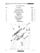
BARREL ASSEMBLY (REFER TO FIGURE 7)
The Barrel Assembly along with the Bolt Carrier Group and Magazine can be changed by the operator / user
to accommodate various calibers.
There are configuration and operational differences between the standard gas tube system and the piston
system.
STANDARD (DIRECT IMPINGEMENT) GAS TUBE SYSTEM (REFER TO FIGURE 7A)
• The barrel (Figure 7A (2)) is threaded at the front to receive the compensator (Figure 7A (3)) and held in
place with a crush washer (Figure 7A (4)). Various compensators are available to match the operator’s
needs. The barrel has a drilled hole which allows gas to be vented through the gas block into the gas tube
(Figure 7A (1)) which is held in place with a roll pin (Figure 7A (5)).
• The gas tube (Figure 7A (1)) is retained by the gas tube pin; and the barrel assembly is retained in the
rear by the upper receiver.
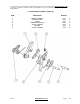
PISTON SYSTEM (REFER TO FIGURE 7B)
• The barrel (Figure 7B (1)) is threaded at the front to receive the compensator (Figure 7B (6)) and held in
place with a crush washer (Figure 7B (7)). Various compensators are available to match the operator’s
needs. The barrel has a piston plug and rod assembly that facilitates the weapons action.
• When the rifle is fired, the developing gases expand inside of the gas block much like a traditional
Standard Gas System (DI). The expanding gases push against the short stroke piston (Figure 7B (5))
which exerts pressure on the operating rod (Figure 7B (3))and thus gives momentum to the bolt carrier.
Once the piston (Figure 7B (4)) itself has travelled less than 1.0 Inch (25MM), it expels any unused gases
from a small vent in the bottom of the piston tube. Once the cycle of the action is in progress, the piston
moves to the back of its chamber awaiting the return of the operating rod to push it back into its normal
resting state.
• The barrel assembly (Figure 7B) is retained in the rear by the upper receiver.
LOWER RECEIVER ASSEMBLY (REFER TO FIGURE 2)
The Lower Assembly provides a means of controlling the fire and safety mechanism. This mechanism consists
of the trigger, hammer (Figure 4), and selector lever (Figure 3). The lower receiver (Figure 2 (25)) also houses
the magazine well and catch (Figure 2 (23)) which allows the operation to hold a multi round magazine (Figure
1 (9)) that is provided. It also houses the buffer (Figure 2 (9)) and spring system (Figure 2 (3)) aids in the cycle
of the weapon.
BOLT CARRIER GROUP (REFER TO FIGURE 9)
The Bolt Carrier Group consists of the Bolt Carrier (Figure 10), Bolt (Figure 11) and Firing Pin (Figure 9 (2)).
This assembly is what operates with the gas system to help in the ejection of the spent cartridge and loads the
next cartridge for firing from the magazine. When the trigger (Figure 4 (6)) is squeezed, it rotates rearward
about its axis, disengaging the sear from the hammer. The hammer then rotates forward under influence of its
own spring (Figure 4 (5)). The front face of the hammer strikes the rear face of the firing pin (Figure 9 (2)),
driving it forward impacting against the rear of the primer in the round. This ignites the propellant in the round,
driving the projectile through the barrel.
The Bolt Carrier Group along with the Barrel Assembly and Magazine can be changed by the operator / user
to accommodate various calibers.
TACTICAL SIGHT UNITS (REFER TO FIGURE 1)
The tactical sight unit comprises of two units, Front Tactical Sight (Figure 1 (1)) and the Rear Tactical Sight
Unit (Figure 1 (2)). The front site post is moved up or down when zeroing the rear sight. Adjustments can be
made by depressing the locking pin with a bullet tip and twisting the post or a special adjustment tool (NSN
9510-00-640-4407). The Tactical Rear Sight has a dual aperture for normal and longer range firing. Windage
adjustments can be made with rear sight.