
Manual


Rev F www.lmtdefense.com Page
28
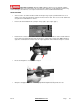
7.62x51mm/308 Win 5.56x45mm Enhanced 5.56x45mm Standard
• The Bolt and Extractor components are now ready for a detailed cleaning. Notice the Enhanced Bolt
has two extractor springs.
REASSEMBLY
• Reassembly is the reverse of stripping.
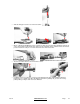
REPLACING BUFFER AND ACTION SPRING
• Ensure the hammer is in the cocked position. Place the return spring onto the buffer. Turn the spring
½ turn clockwise to ensure it is seated correctly.
• Replace the buffer and action spring into the butt of the lower receiver. Depress the buffer retaining
pin with a suitable drift and push the buffer into the butt. Release the buffer retaining pin and, while
maintaining control, allow the buffer to move forward under influence of its spring. Ensure the buffer
retaining pin has reasserted itself and retains the buffer.
REASSEMBLY OF UPPER AND LOWER RECEIVER
• Align the upper and lower receiver together in the open position. Ensure locking pin holes are aligned.
Push the forward front pivot pin from right to left.
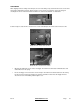
REASSEMBLY OF BOLT AND CARRIER
• Replace the bolt into the carrier.
• NOTE: Ensure the cam pinhole with the two indentations is to the bottom. Align the cam pinhole in the
bolt with the rear of the cam recess in the carrier.
• Replace the cam pin. Rotate the cam pin to align its firing pin hole with the axis of the bolt.
IT IS ESSENTIAL THAT THE CAM PIN IS REPLACED AT THIS POINT. FAILURE TO
REPLACE THE CAM PIN MAY CAUSE A DANGEROUS SITUATION DURING FIRING CAUSING
PERSONAL INJURY OR DEATH.
• Insert the firing pin through the rear of the carrier and ensure it is fully seated. Pull the bolt fully
forward into the locked position. Replace the firing pin retaining pin from the left side of the carrier.
Verify that when the bolt is fully inserted into the Bolt Carrier, push on the back side of the firing pin to
verify that the pin is protruding out the bolt face.
REPLACING THE BOLT AND CARRIER ASSEMBLY
• Replace the charging handle by engaging the expanded end into the recess in the upper receiver
guide way. Partially push the charging handle forward.
• Ensure the bolt is in the unlocked position in the carrier. Align the carrier key to the recess in the
underside of the charging handle. Slide the carrier assembly into the upper receiver. Push the carrier
assembly and the charging handle forward until a distinctive click is heard, then they are fully located
into the upper receiver.
• In the lower assembly, push the hammer back into the cocked position. Once this is done, make
sure the selector lever in the “Safe” position.
• Join the upper and lower receiver together. Push the rear takedown pin into the lower receiver from
the right hand side.