
Manual


Rev F www.lmtdefense.com Page
19
ACTION OF MECHANISM
LOADING PROCEDURES AND FUNCTION BEFORE FIRING
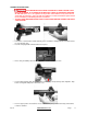
The weapon is initially cocked, before firing, by pulling the charging handle (Figure 1 (4)) completely to the
rear, which will cause the bolt carrier group (Figure 1 (3)) to move rearwards.
As the carrier moves rearward, it contacts the hammer, forcing it to rotate rearwards about its axis, cocking on
the trigger.
• Empty magazine fitted. The magazine platform will actuate the bolt catch and hold the bolt carrier group to
the rear.
• Loaded magazine fitted. The bolt catch must be operated manually by pressing on the lower projection of
the bolt catch, to hold the bolt carrier group to the rear.
• No magazine fitted: The bolt catch must be operated manually by pressing on the lower projection of the
bolt catch, to hold the bolt carrier group to the rear.
LOAD
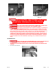
With a loaded magazine on the weapon and the bolt carrier group to the rear, actuation of the bolt catch will
allow the bolt carrier group to be driven forward under influence of the return spring (Figure 2 (3)).
As the carrier moves forward, the lugs of the bolt contact the base of the top round in the magazine, and feed
it into the chamber.
As the bolt locking lugs enter the barrel extension the round is stopped by the shoulders in the chamber. The
ejector (Figure 11 (6)) is pushed against the left side of the round base placing the ejector spring under
tension. The extractor (Figure 11 (2)) over-rides the round rim and snaps into the extractor groove on the right
side of the round base.
LOCK
Forward motion of the bolt is stopped by the chamber. The bolt carrier continues to move forward until it is
stopped by contact with the rear face of the barrel extension. At the same time, the bolt cam pin (Figure 9A
(4)) contacts the angled face of the carrier cam slot, forcing the bolt to rotate. The bolt lugs rotate behind the
barrel extension lugs, locking the bolt.
FIRE
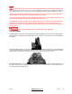
With the fire selector lever (Figure 3) set to “Fire” and/or “Auto” the weapon may be fired. When the trigger
(Figure 4 (6)) is squeezed, it rotates rearward about its axis, disengaging the sear from the hammer. The
hammer then rotates forward under influence of its own spring (Figure 4 (5)). The front face of the hammer
strikes the rear face of the firing pin, driving it forward impacting against the rear of the primer in the round.
This ignites the propellant in the round, driving the projectile through the barrel.
UNLOCK
The projectile is forced through the barrel by the propellant gases. As the projectile passes the gas port some
of the gases are bled off, passing along the gas tube (Figure 7A (1)), into bolt carrier key (Figure 10 (1)) and
then into the cylindrical section in the bolt carrier, where it fills the chamber behind the bolt.
The expansion of the gases begins to drive the bolt carrier rearwards.
During initial rearward movement of the bolt carrier, the bolt remains locked as the straight section of the bolt
carrier cam slot moves un-obstructed over the bolt cam pin. This allows gas pressures in the bore to drop to a
safe level before unlocking starts. (This is the dwell time.)
As the bolt carrier continues rearward, the angled face of the bolt carrier cam slot impinges on the bolt cam
stud, forcing the bolt to rotate. This rotation of the bolt allows the lugs on the bolt to clear the lugs of the barrel
extension. This allows unimpeded rearward movement, and as such unlocks the bolt from the barrel
extension.
The bolt and bolt carrier continue to move rearwards.