OPERATION and SAFETY MANUAL LMT Manufactured MRP™ WEAPON SYSTEM BE A SAFE AND RESPONSIBLE GUN OWNER - BEFORE HANDLING YOUR WEAPON READ AND UNDERSTAND THE SAFETY INFORMATION INSIDE THIS DOCUMENT READ AND UNDERSTAND HOW TO OPERATE THIS FIREARM ALWAYS OPERATE FIREARMS LEGALLY AND SAFELY ALWAYS STORE ALL FIREARMS SAFELY AND RESPONSIBLY Lewis Machine & Tool Co. th 1305 W. 11 St. - Milan, IL 61264 USA Main: 309.787.7151 – Fax: 309.787.7193 Sales: 309.732.9527 – Fax: 309.787.2636 Email: sales@lmtdefense.
CONTENTS Rev F Introduction Equipment Identification Nomenclatures Rules for Safe Gun Handling Rules for Safe Gun Handling with Sling Maintenance Before Storage Storage / Transportation Loading / Unloading Firearm Preparation for Firing Sighting Adjustments Ammunition Cleaning and Maintenance Cleaning and Maintenance of Piston System Action of Mechanism Piston System - Modes Trouble Shooting Field Stripping - Assembly ~ Disassembly Function / Operation Limited Warranty Weapon - General Specification 3 4
THE MRP™ WEAPON SYSTEM IS AN AUTOLOAD FIREARM. DO NOT ATTEMPT TO LOAD, OPERATE OR FIRE BEFORE READING AND UNDERSTANDING THE SAFETY INFORMATION IN THIS MANUAL. THE MRP™ WEAPON SYSTEM IS A MAGAZINE FEED CENTERFIRE AUTOLOADING RIFLE. THE RIFLE WILL CONTINUE TO FIRE EACH TIME THE TRIGGER IS PULLED UNTIL THE RIFLE IS UNLOADED OR THE AMMUNITION IN THE MAGAZINE HAS BEEN DEPLEATED. IF A CARTRIDGE IS IN THE CHAMBER, THE WEAPON WILL FIRE EVEN IF THE MAGAZINE IS EMPTY OR THE MAGAZINE HAS BEEN REMOVED FROM THE FIREARM.
LMT Manufactured MRP™ Weapon System firearms are reliable and safe to use when the firearm safety rules are followed. There are a number of internal safety mechanisms within the internal mechanism of the firearm which ensure that the firearm will not discharge unless the trigger of the firearm is pulled. NEVER RELY ON MECHANICAL FEATURES ALONE. Only your safe gun-handling habits will ensure the safe use of your firearm. This is your responsibility.
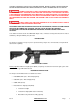
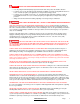
NOMENCLATURE Buttstock Assy Rear Sight Assy Brass Deflector Upper Receiver Magazine Stock Release Lever Takedown Pin Trigger Front Sight Barrel Assy Compensator Magazine Release LM308MWS, Rifle (Gas-Direct Impingement) Serial Number Charging Handle Forward Assist Bolt Carrier Ambidextrous Safety Selector Lever Pistol Grip Front Sight Ambidextrous Bolt Catch Magazine Release CQB, Rifle (Gas-Direct Impingement) Trigger Guard Locking Screws Gas Piston Plug CQB, Rifle (Gas-Piston) Quick D
RULES FOR SAFE GUN HANDLING To safely and properly handle this firearm, you must understand that injury or death to you or others may result from unsafe or careless use. It must be kept in mind that while the general rules of safe gun handling always apply, circumstances or conditions may exist that require additional precautions to be taken.
CAUTION !.. RULES FOR SAFE GUN HANDLING WHEN UTILIZING A SLING • • • • Use only slings that will adequately support the firearm and safely control the muzzles direction If a sling is to be used, unload the firearm and practice pulling it on and off, moving with the firearm on foot, in a vehicle (if legal in your application) or using in various firing positions If a sling is to be used with a vest, packs, etc.
NEVER KEEP AMMUNITION IN THE SAME LOCATION AS THE FIREARM. Store each in a separate and secure place. ALWAYS WEAR EYE AND EAR PROTECTORS THAT ARE SPECIFIED FOR FIREARM USE EVERY TIME YOU DISCHARGE YOUR FIREARM. Make sure others in the vicinity of where you will be shooting do so as well. NEVER USE ALCOHOL OR DRUGS BEFORE OR WHILE SHOOTING. Do not use your firearm if you are on any medication which impairs, even slightly, your mental or physical ability. ALWAYS HAVE ADEQUATE VENTILATION.
MAINTENANCE BEFORE STORAGE When storing, do not encase your firearm in anything that will attract or hold moisture, for example, leather or heavy cloth. Also, do not store guns with a plug inserted in the barrel for this can be a contributing factor to moisture accumulation. If your firearm is to be stored for an extended period, the bore, the chambers and internal working mechanism should be oiled with a high quality lubricating oil or preservative intended for firearms.
BEWARE OF DANGEROUS CONDITIONS • • • • • • • • • Be sure Cam Pin is installed in the Bolt Group. If it isn’t, your firearm can still fire and COULD MALFUNCTION, CAUSING PROPERTY DAMAGE, PERSONAL INJURY OR DEATH. When using a Blank Firing Attachment, never fire anything except blank ammunition! For your safety, we recommend the visible, LMT™ blank firing system that includes a special magazine, barrel and barrel bullet trap.
LOADING RIFLE AND FIRING • • • THIS FIREARM MAY DISCHARGE ACCIDENTALLY WHEN A ROUND IS FED INTO THE CHAMBER. IF IT IS DROPPED OR RECEIVES A BLOW TO THE MUZZLE OR FRONT OF THE GUN. (This can occur regardless of the position of the hammer or any of the various safety devices.) Therefore, extra care and strict adherence to these instructions by the firearm user is mandatory for minimizing the risk of accidents. ALWAYS READ AND UNDERSTAND SAFETY INSTRUCTIONS BEFORE LOADING AND FIRING YOUR FIREARM.
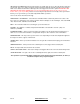
Fire Selection – Semi Automatic Fire Selection – Full Automatic (Optional) - Rifle is now loaded. Keep it pointed in a safe direction If you rotate the safety from “SAFE” to “FIRE” position… THE RIFLE WILL FIRE WHEN YOU PULL THE TRIGGER • THIS IS AN AUTOLOADING FIREARM AND IS IMMEDIATELY LOADED AND READY TO FIRE AGAIN AFTER EACH SHOT UNTIL THE CHAMBER IS EMPTY. • If your firearm stops firing with a live round in the chamber of a hot barrel (a misfire).
• Rotate safety to the “SAFE” position if possible. (If hammer is not cocked, safety cannot be rotated to “SAFE”.) • Remove magazine by pushing in magazine catch button while pulling magazine from receiver. • Pull charging handle fully to the rear and lock bolt to the rear by pressing on the lower portion of the bolt catch. If not done so already place safety on “SAFE”. • Inspect chamber and inside of receiver areas for cartridge or brass. Remove any round and other debris.
ALWAYS WEAR SAFETY GLASSES SPECIFIED FOR FIREARMS USE, WHETHER INDOORS OR OUT. Safety glasses should protect your eyes from the firing flash and particles associated with the discharge of ammunition. Failure to do so creates a risk of personal injury from particle or debris spitting or ricochets. ALWAYS BE ALERT AND ALWAYS FOLLOW THE SAFETY INSTRUCTIONS OF THE RANGE OFFICER. NEVER SHOOT IF YOU ARE TIRED, COLD OR IMPAIRED IN ANY WAY.
AMMUNITION All Lewis Machine & Tool Co. products are designed and built to specifications to shoot standard factory commercially available NATO compliant ammunition. The specifications for standard commercially available NATO compliant ammunition include harder primers to withstand the slight indentation from the firing pin when the bolt chambers a cartridge. This slight indentation is normal.
IF THERE IS ANY REASON TO SUSPECT THAT A BULLET IS OBSTRUCTING THE BARREL, IMMEDIATELY UNLOAD THE FIREARM AND LOOK THROUGH THE BORE. IT IS NOT SUFFICIENT TO MERELY LOOK IN THE CHAMBER. A BULLET MAY BE LODGED SOME DISTANCE DOWN THE BARREL WHERE IT CANNOT EASILY BE SEEN. IF A BULLET IS IN THE BORE, DO NOT ATTEMPT TO SHOOT IT OUT BY USING ANOTHER CARTRIDGE, OR BY BLOWING IT OUT WITH A BLANK OR ONE FROM WHICH THE BULLET HAS BEEN REMOVED.
CAUTION !.. Never fire any semi-automatic and/or fully automatic firearm with your finger, hand, face, or other part of your body over or adjacent to the ejection port, or in any position where you may be struck by the reciprocating movement of the operating bolt or carrier group.
CAUTION !.. Some cleaners can cause damage to your firearms. You should avoid prolonged solvent immersion and prolonged ultrasonic cleaning of your firearm. Choice of solvent should be restricted to those products specifically developed for firearms maintenance. Damage to a firearm’s finish may occur if these cautions are ignored. Ammoniated solvents or other strong alkaline solvents should not be used on any Lewis Machine & Tool Co. firearm.
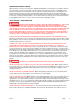
ACTION OF MECHANISM LOADING PROCEDURES AND FUNCTION BEFORE FIRING The weapon is initially cocked, before firing, by pulling the charging handle (Figure 1 (4)) completely to the rear, which will cause the bolt carrier group (Figure 1 (3)) to move rearwards. As the carrier moves rearward, it contacts the hammer, forcing it to rotate rearwards about its axis, cocking on the trigger. • Empty magazine fitted. The magazine platform will actuate the bolt catch and hold the bolt carrier group to the rear.
EXTRACTION As the bolt moves rearward, the extractor which is pinned to the bolt and engaged in the canullar groove of the empty cartridge, withdraws the cartridge from the chamber. EJECTION The empty cartridge which is still held by the extractor (Figure 11 (2)) is withdrawn from the chamber. As the cartridge clears the barrel extension and inline with the ejection port, the spring on the ejector re-asserts, forcing the base of the cartridge to rotate about the extractor.
TROUBLE SHOOTING Shown in table 1. The trouble shooting guide does not cover all theoretical malfunctions. This also applies to suggested causes and corrective action. Qualified gunsmiths or armourers only must carry out repairs.
EQUIPMENT DAMAGE. When the MRP™ Weapon System is in the stripped condition never release the hammer uncontrolled from the cocked position. Failure to comply with this instruction may result in damage to the hammer, sear components and lower receiver and will void all warranties, FIELD STRIPPING • Various tasks to assemble and disassemble the weapon may require specialized armourer’s tools (Figure 13) to safely and effectively complete the mission and or task.
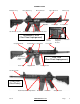
• With the charging handle held to the rear, depress the bolt release catch with the thumb of the left hand. Slowly allow the charging handle to return forward until the working parts contact the bolt release catch. The bolt will now be retained by the bolt release catch, and the charging handle should be pushed fully forward. Return the right hand to the pistol grip, and control the weapon with the left hand on the hand-guard. • Tilt the weapon over to the left.
• From the left-hand side push the rear locking pin to the right. From the right-hand side, pull the rear takedown pin until it comes to a positive stop. • From the left-hand side push the rear locking pin to the right. From the right-hand side, pull the front pivot pin until it comes to a positive stop. • • Separate the upper and lower receivers. • • With the hammer in cocked position, depress the buffer retainer. Remove the buffer and recoil spring.
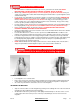
NOTE: Standard carbines use the standard unmarked buffer. All piston operated rifles use the H2 buffer. The LM308MWS uses the H3 buffer. BARREL REMOVAL AND INSTALLATION (REFER TO FIGURE 5A) • • Removing Barrel from Upper Receiver o NOTE: BARREL MUST BE COOL TO THE TOUCH BEFORE PROCEEDING WITH BARREL REMOVAL AND INSTALLATION. o If a carrier group exists, remove it from the upper receiver. o Using a T-30 Torx wrench, remove the front bolt (1) from the receiver.
• Pull the plug/operating rod from the gas block. The piston should come with the plug due to the highquality fit. • The piston is easy to remove from the plug with gentle hand pressure. REMOVING THE BOLT AND CARRIER ASSEMBLY • Pull the charging handle to the rear. Remove the bolt carrier assembly from the upper receiver.
• • • • Rev F Slide the firing pin out of the rear of the bolt carrier. 7.62x51mm/308 Win 5.56x45mm 5.56x45mm On the 7.62x51mm/308 Win bolt carrier, rotate the bolt into the locked position and lift the cam pin out of the carrier. On the 5.56mm direct gas and piston operated bolt carriers rotate the bolt to the locked position. Rotate the cam pin ¼ of a turn and remove it from the bolt carrier 7.62x51mm/308 Win The bolt can now be Remove the bolt from the carrier. 5.
• 7.62x51mm/308 Win 5.56x45mm Enhanced 5.56x45mm Standard The Bolt and Extractor components are now ready for a detailed cleaning. Notice the Enhanced Bolt has two extractor springs. REASSEMBLY • Reassembly is the reverse of stripping. REPLACING BUFFER AND ACTION SPRING • Ensure the hammer is in the cocked position. Place the return spring onto the buffer. Turn the spring ½ turn clockwise to ensure it is seated correctly. • Replace the buffer and action spring into the butt of the lower receiver.
REPLACING ACCESSORIES • Replace the sights, sling and any other accessories if applicable. INSTALLATION AND REMOVAL OF SOPMOD BUTTSTOCK • Removing Buttstock from Extension Tube • Grasp the release lever (Figure 12 (5)) on the checkered end. While pulling the release lever away from the buttstock, slide the buttstock (Figure 12 (3)) off the end of the extension tube (Figure 2 (2)).
FUNCTIONING After stripping and reassembly of the weapon, the user must always carry out the function test to ensure that all operations will function properly. Tilt the weapon over to the left. Look into the ejection opening port ensuring the front face of the bolt and the chamber are clear from ammunition or obstructions. Cock the weapon, rotate the fire selector lever to “Safe” and attempt to fire off the action. It must not fire. Rotate the fire selector lever to “Fire”.
ONE YEAR LIMITED WARRANTY Lewis Machine and Tool Co. warrants to the initial retail purchaser that LMT™ firearm will be free of defects in workmanship and material for a period of one year from the date of purchase. Any such defects of which Lewis Machine and Tool Co. is given written notice within one year and ten days from the date of the initial retail purchase by the initial retail purchaser will be remedied by Lewis Machine and Tool Co. as provided below.
WEAPON – GENERAL SPECIFICATION TABLE 1 LMT™ MODULAR WEAPON SYSTEM CHARACTERISTICS MECHANICAL FEATURES Characteristic LM308MWS CQB (5.56MM) CQB (6.8MM) GAS AND MAGAZINE FED GAS AND MAGAZINE FED GAS AND MAGAZINE FED METHOD OF LOCKING ROTATING BOLT ROTATING BOLT ROTATING BOLT NUMBER OF GROOVES SS = 5 RIGHT HAND CR-MO-V = 5 RIGHT HAND 6 RIGHT HAND 6 RIGHT HAND PITCH OF RIFLING - 1 TURN IN SS = 286MM / 11.25 IN CR-MO-V = 254MM / 10.0 IN 177.8 MM 7.0 IN 254 MM 10.
BARREL ASSEMBLY (REFER TO FIGURE 7) The Barrel Assembly along with the Bolt Carrier Group and Magazine can be changed by the operator / user to accommodate various calibers. There are configuration and operational differences between the standard gas tube system and the piston system. STANDARD (DIRECT IMPINGEMENT) GAS TUBE SYSTEM (REFER TO FIGURE 7A) • The barrel (Figure 7A (2)) is threaded at the front to receive the compensator (Figure 7A (3)) and held in place with a crush washer (Figure 7A (4)).
You can now access spare parts, replacement parts and accessories by going to www.lmtdefense.com. If you prefer to speak to a customer service representative, or do not see the item listed please contact us at 309.732.9527.
You can now access spare parts, replacement parts and accessories by going to www.lmtdefense.com. If you prefer to speak to a customer service representative, or do not see the item listed please contact us at 309.732.9527. LOWER ASSEMBLY – SEMI AUTOMATIC (FIGURE 2A) ITEM DESCRIPTION Quantity 1 2 3 4 5 6 7 8 9 10 11 12 13 14 15 16 17 19 20 21 22 23 24 25 26 27 28 29 30 31 32 BUTTSTOCK SOPMOD TUBE, RECEIVER EXTENSION SPRING, ACTION SLING LOOP REC.
FIGURE 2A Rev F www.lmtdefense.
You can now access spare parts, replacement parts and accessories by going to www.lmtdefense.com. If you prefer to speak to a customer service representative, or do not see the item listed please contact us at 309.732.9527. LOWER ASSEMBLY – FULL AUTOMATIC (FIGURE 2B) ITEM DESCRIPTION Quantity 1 2 3 4 5 6 7 8 9 10 11 12 13 14 15 16 17 19 20 21 22 23 24 25 26 27 28 29 30 31 32 BUTTSTOCK SOPMOD TUBE, RECEIVER EXTENSION SPRING, ACTION SLING LOOP REC.
FIGURE 2B Rev F www.lmtdefense.
You can now access spare parts, replacement parts and accessories by going to www.lmtdefense.com. If you prefer to speak to a customer service representative, or do not see the item listed please contact us at 309.732.9527. SELECTOR AMBI SEMI / FULL AUTO ASSEMBLY (FIGURE 3) ITEM DESCRIPTION QUANTITY 1 2 3 6-32 FLATHEAD SCREW LEFTY, FIRE SWITCH SELECTOR AMBI SEMI 1.0000 1.0000 1.0000 Rev F www.lmtdefense.
You can now access spare parts, replacement parts and accessories by going to www.lmtdefense.com. If you prefer to speak to a customer service representative, or do not see the item listed please contact us at 309.732.9527. 2 STAGE TRIGGER ASSEMBLY (FIGURE 4A) ITEM DESCRIPTION QUANTITY 1 2 3 4 5 6 7 HAMMER ASSEMBLY DISCONNECTOR SPRING HAMMER-TRIGGER PIN SPRING, TRIGGER TRIGGER SPRING, HAMMER 1.0000 1.0000 1.0000 2.0000 1.0000 1.0000 1.0000 Rev F www.lmtdefense.
You can now access spare parts, replacement parts and accessories by going to www.lmtdefense.com. If you prefer to speak to a customer service representative, or do not see the item listed please contact us at 309.732.9527. FULL AUTOMATIC TRIGGER ASSEMBLY (FIGURE 4B) ITEM DESCRIPTION QUANTITY 1 2 3 4 5 6 7 HAMMER ASSEMBLY DISCONNECTOR SPRING HAMMER-TRIGGER PIN SPRING, TRIGGER TRIGGER SPRING, HAMMER 1.0000 1.0000 1.0000 2.0000 1.0000 1.0000 1.0000 Rev F www.lmtdefense.
You can now access spare parts, replacement parts and accessories by going to www.lmtdefense.com. If you prefer to speak to a customer service representative, or do not see the item listed please contact us at 309.732.9527. UPPER ASSEMBLY (FIGURE 5) ITEM DESCRIPTION QUANTITY 1 2 ASSEMBLY, UPPER RECEIVER BARREL ASSEMBLY 1.0000 1.0000 ea ea Page 42 FIGURE 5A Rev F www.lmtdefense.
You can now access spare parts, replacement parts and accessories by going to www.lmtdefense.com. If you prefer to speak to a customer service representative, or do not see the item listed please contact us at 309.732.9527. UPPER RECEIVER ASSEMBLY (FIGURE 6) ITEM DESCRIPTION Quantity 1 2 3 4 5 6 7 8 WASHER, FLAT SS SCREW, LOCKING PIN, ROLL, BOLT CATCH RING, RETAINING, EJECTION PIN, EJECTION PORT COVER EJECTION PORT COVER SPRING, EJECTION PORT RECEIVER, UPPER 1.0000 2.0000 2.0000 1.0000 1.0000 1.0000 1.
You can now access spare parts, replacement parts and accessories by going to www.lmtdefense.com. If you prefer to speak to a customer service representative, or do not see the item listed please contact us at 309.732.9527. BARREL ASSEMBLY – GAS/DI (FIGURE 7A) ITEM DESCRIPTION Quantity 1 2 3 4 5 ASSEMBLY, GAS TUBE BARREL SUB ASSEMBLY THREAD COMPENSATOR SHIM WASHERS PIN, ROLL, GAS TUBE 1.0000 1.0000 1.0000 1.0000 1.0000 Rev F www.lmtdefense.
You can now access spare parts, replacement parts and accessories by going to www.lmtdefense.com. If you prefer to speak to a customer service representative, or do not see the item listed please contact us at 309.732.9527. BARREL ASSEMBLY - PISTON (FIGURE 7B) ITEM DESCRIPTION Quantity 1 2 3 4 5 6 7 BARREL SUB ASSEMBLY SPRING, COMPRESSION PISTON, GAS RING, PISTON PLUG, GAS PISTON THREAD COMPENSATOR SHIM WASHERS 1.0000 1.0000 1.0000 1.0000 1.0000 1.0000 1.0000 Rev F www.lmtdefense.
FIGURE 7C FIGURE 7D FIGURE 7E Rev F www.lmtdefense.
You can now access spare parts, replacement parts and accessories by going to www.lmtdefense.com. If you prefer to speak to a customer service representative, or do not see the item listed please contact us at 309.732.9527. CHARGING HANDLE ASSEMBLY (FIGURE 8) ITEM DESCRIPTION QUANTITY 1 2 3 4 PIN, CHARGING HANDLE SPRING, CHARGING HANDLE TACTICAL CHARGING HANDLE LATCH HANDLE, CHARGING 1.0000 1.0000 1.0000 1.0000 Rev F www.lmtdefense.
You can now access spare parts, replacement parts and accessories by going to www.lmtdefense.com. If you prefer to speak to a customer service representative, or do not see the item listed please contact us at 309.732.9527. CARRIER GROUP ASSEMBLY – GAS/DI (FIGURE 9A) ITEM DESCRIPTION QUANTITY 1 2 3 4 CARRIER ASSEMBLY FIRE PIN BOLT ASSEMBLY CAM PIN 1.0000 1.0000 1.0000 1.0000 ea ea ea ea Page 48 Rev F www.lmtdefense.
You can now access spare parts, replacement parts and accessories by going to www.lmtdefense.com. If you prefer to speak to a customer service representative, or do not see the item listed please contact us at 309.732.9527. CARRIER GROUP ASSEMBLY - PISTON (FIGURE 9B) ITEM DESCRIPTION QUANTITY 1 2 3 4 5 CARRIER FIRING PIN PIN, RETAINING, FIRING BOLT ASSEMBLY CAM PIN 1.0000 1.0000 1.0000 1.0000 1.0000 Rev F www.lmtdefense.
You can now access spare parts, replacement parts and accessories by going to www.lmtdefense.com. If you prefer to speak to a customer service representative, or do not see the item listed please contact us at 309.732.9527. CARRIER ASSEMBLY (FIGURE 10) ITEM DESCRIPTION QUANTITY 1 2 3 4 5 KEY, GAS SCREW, SOCKET HEAD CAP PIN, SPRING SLOTTED CARRIER, BOLT RETAINING PIN, FIRE PIN 1.0000 2.0000 1.0000 1.0000 1.0000 Rev F www.lmtdefense.
You can now access spare parts, replacement parts and accessories by going to www.lmtdefense.com. If you prefer to speak to a customer service representative, or do not see the item listed please contact us at 309.732.9527. BOLT ASSEMBLY (FIGURE 11) ITEM DESCRIPTION QUANTITY 1 2 3 4 5 6 7 8 9 BOLT EXTRACTOR SPRING BUFFER SPRING EJECTOR EJECTOR EJECTOR, RETAINING PIN EXTRACTOR PIVOT PIN GAS RING ASSEMBLY 1.0000 1.0000 1.0000 1.0000 1.0000 1.0000 1.0000 1.0000 1.0000 Rev F www.lmtdefense.
You can now access spare parts, replacement parts and accessories by going to www.lmtdefense.com. If you prefer to speak to a customer service representative, or do not see the item listed please contact us at 309.732.9527. BUTTSTOCK ASSEMBLY (FIGURE 12) ITEM DESCRIPTION QUANTITY 1 2 3 4 5 6 7 8 9 10 SPRING PIN, LOCK SOPMOD ASSEMBLY W/LRG HOLE BUTTPLATE LEVER, RELEASE PIN, SPRING NUT, LOCK PIN TUBE O-RING CAP 1.0000 1.0000 1.0000 1.0000 1.0000 1.0000 1.0000 2.0000 4.0000 2.0000 Rev F www.lmtdefense.
You can now access spare parts, replacement parts and accessories by going to www.lmtdefense.com. If you prefer to speak to a customer service representative, or do not see the item listed please contact us at 309.732.9527.
Firearm Maintenance Record Date Rev F Service Performed www.lmtdefense.
Rev F www.lmtdefense.
Rev F www.lmtdefense.
Rev F www.lmtdefense.
Lewis Machine & Tool Co. th 1305 W. 11 St. - Milan, IL 61264 USA Main: 309.787.7151 – Fax: 309.787.7193 Sales: 309.732.9527 – Fax: 309.787.2636 Email: sales@lmtdefense.com Rev F www.lmtdefense.