
System Manual
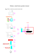


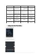


Terminal 1: power port:From left to right: GND ,power(12V) .
Terminal 2: security port:From left to right: F1~F10 ,Output alarm sensor.
Terminal 3:RS485 port:From left to right:485A ,485B
Terminal 4: Dry contact output port:From left to right: K1 ,K2, for Calling the
elevator
Terminal 5:Doorbell bus interface: From left to right: 12V ,GND,NC,DATA.
Terminal 6:From left to right:GND,XVI, Connect the visual doorbell video output
interface.
Terminal 7:From left to right:GND, XVO, Connect the next smart screen video
input connection mouth
Terminal 8: Usb interface:From left to right:5V ,-D,+D,GND
Terminal 9:Program entry:From left to right:5V ,-D,+D,GND, Connect USB port
of computer
Terminal 10: Ethernet interface:Connecting LAN Switches, Used for TCP/IP
communication
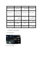
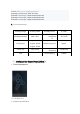
3、Technical parameters