
Install Instructions

PK-A3216-10-00-0B
For Technical Assistance Call: 1-800-824-3005 (U.S.A. Only)
1 800 405-5320 (Canada Only) www.leviton.com
PK-A3216-10-00-0B
IMPORTANT SAFETY INSTRUCTIONS - READ ALL INSTRUCTIONS BEFORE USING.
INSTALLATION INSTRUCTIONS
Nos. LDCxx, LDCxx-W
© 2017 Leviton Mfg. Co., Inc.
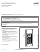
Cover and Door Assembly
PATENTS PENDING
LIMITED PRODUCT WARRANTY
For Leviton’s limited product warranty, go to www.leviton.com. For a printed copy of the warranty you may call 1-800-323-8920.
WARNING
Fig. 1
• TO AVOID FIRE, SHOCK OR DEATH: TURN OFF POWER SUPPLYING THIS EQUIPMENT, AND CONFIRM POWER IS OFF,
before installing, removing or servicing this equipment.
• This equipment MUST BE installed and serviced by an electrician.
• Replace all doors and covers before connecting power to this equipment.
• To be installed and/or used in accordance with electrical codes and regulations.
Twist-outs
(B)
Main
breaker
knockout
(A)
INSTALLATION
WARNING: TO AVOID FIRE, SHOCK OR DEATH: TURN OFF POWER
SUPPLYING THIS EQUIPMENT, AND CONFIRM POWER IS OFF,
before installing, removing or servicing this equipment.
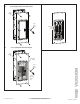
Installing Cover
1.
Remove the main breaker knockout (A) from deadfront (F) if a main
breaker was installed. Do not remove in installations using the main lugs.
2. Twist-outs (B) must be removed for each position that contains a branch
circuit breaker.
3. To remove twist-outs (B), first strike with a screwdriver, then twist with
pliers until detached (fig. 1).
NOTE: Fill any unused open spaces in cover using filler plates
(see filler plate instructions).
4. Apply circuit directory label. For observation window door units, apply
labels to the deadfront (F) area shown (Fig. 2b). For solid door units
apply labels to the back of the door.
NOTE: Apply pocket to door if desired.
5. Install cover assembly (C) using the six (x6) cover screws (D)
(provided) (fig. 2).
6. Leviton
®
covers contain a feature for adjustment in flush mounting
applications. Turn each adjustment screw (E) until the cover fits tightly
against the circuit breakers (fig.3).
SAVE THESE INSTRUCTIONS
Deadfront
(F)
WEB VERSION