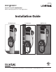
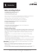
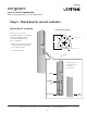
evr-green™ Level 1 / Level 2 Combination Network Charging Station For Public Applications Installation Guide Bollard Mount Pole Mount Wall Mount C US Listed lll#aZk^idc#Xdb$Zkg\gZZc &"-,,"((-",),( Zkg\gZZc5aZk^idc#Xdb
evr-green™ Level 1 / Level 2 Combination Network Charging Station For Public Applications IMPORTANT SAFETY INSTRUCTIONS H6K: I=:H: >CHIGJ8I>DCH I]^h bVcjVa XdciV^ch ^bedgiVci ^chigjXi^dch i]Vi bjhi WZ [daadlZY Yjg^c\ ^chiVaaVi^dc d[ V :kg"
evr-green™ Level 1 / Level 2 Combination Network Charging Station For Public Applications Table of Contents 1 Introduction Before installing stations .................................. .............................................................................................................. &"& HeZX^ÒXVi^dch####################################################################################### ............................................................................... &"' L^g^c\ ^c[dgbVi^dc #######
evr-green™ Level 1 / Level 2 Combination Network Charging Station For Public Applications Table of Contents 5 Installing the holster and cable assembly Before you start...................................................................................... ........................................................................... *"& Overview of steps.................................................................................. ...........................................................................
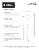
™ evr-green Introduction 1 Level 1 / Level 2 Combination Network Charging Station For Public Applications Before Installing Stations The charging station is divided in to 3 Sections: &# Bdjci^c\ 6hhZbWan l]^X] ^chiVaah Òghi 2.) Cable Assembly which installs second (# =ZVY Jc^i l]^X] ^chiVaah i]^gY VcY aVhi EaZVhZ hZZ i]Z AZkZa &$AZkZa ' EjWa^X JhZ 8]Vg\^c\ HiVi^dc EgdYjXi 7jaaZi^c [dg eVgi cjbWZg VcY dimensional details. To download the bulletin, go to www.leviton.com/evrgreen.
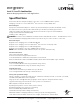
evr-green™ Level 1 / Level 2 Combination Network Charging Station For Public Applications Specifications >chZgi VWdkZ :aZXig^XVa >ceji/ 8]Vg\^c\ XdccZXi^dc " AZkZa &/ C:B6 *"'%G gZXZeiVXaZ 8]Vg\^c\ XdccZXi^dc " AZkZa '/ H6: ?&,,'TM :K XdccZXidg dc &-É *#)-b XVWaZ Electrical input >ceji edlZg/ '%-$')%K (%6 A^cZ & VcY A^cZ ' VcY &'%K &+6 A^cZ! CZjigVa! VcY :Vgi] " * l^gZ GZXdbbZcYZY hZgk^XZ eVcZa WgZV`Zg/ )%6 YdjWaZ edaZ WgZV`Zg cdc"<;8> ineZ VcY '%6 h^c\aZ edaZ WgZV`Zg cdc"<;8> ineZ dc YZY^XViZY
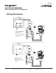
evr-green™ Level 1 / Level 2 Combination Network Charging Station For Public Applications Wiring information !"#$%&&'()&*&+(,-)&*&+(.( /0123'4530'(654530' 40A, 2 POLE BREAKER MAY BE CONNECTED TO ANY TWO PHASES 20A, SINGLE POLE BREAKER MAY BE CONNECTED TO ANY PHASE. !"#$%&&'()&*&+(,-)&*&+(.( /0123'4530'(654530' 20A, S20A, SINGLE POLE BREAKER MAY BE CONNECTED TO EITHER PHASEINGLE POLE BREAKER lll#aZk^idc#Xdb$Zkg\gZZc &"-,,"((-",),( Zkg\gZZc5aZk^idc#Xdb 1-3
evr-green Installing™a 2 Level 1Bollard / Level 2 Mount Combination Network Charging Station For Public Applications Before you start >chiVaaZg"hjeea^ZY XdbedcZcih/ You will need: :kg"
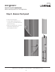
evr-green™ Level 1 / Level 2 Combination Network Charging Station For Public Applications Step 1 - Check box for correct contents Bollard Mount Assembly Bollard Mounting Template :kg"
evr-green™ Level 1 / Level 2 Combination Network Charging Station For Public Applications Step 2 - Remove front panel To remove the front panel: JhZ i]Z hjeea^ZY VaaZc lgZcX] id loosen the 2 screws that fasten the panel to the body. GZbdkZ i]Z \gdjcY l^gZ XdccZXidg [gdb ^ih iVW# Ha^YZ i]Z [gdci panel upward to remove. lll#aZk^idc#Xdb$Zkg\gZZc &"-,,"((-",),( Zkg\gZZc5aZk^idc#Xdb 2-3
evr-green™ Level 1 / Level 2 Combination Network Charging Station For Public Applications Step 3 - Remove mounting pole and base plate from body To remove the body: JhZ i]Z hjeea^ZY VaaZc lgZcX] id addhZc i]Z ) hZi hXgZlh ' dc ZVX] WgVX`Zi # A^[i i]Z WdYn jelVgY# Loosen the four set screws to remove the pole. lll#aZk^idc#Xdb$Zkg\gZZc &"-,,"((-",),( Zkg\gZZc5aZk^idc#Xdb 2-4
evr-green™ Level 1 / Level 2 Combination Network Charging Station For Public Applications Step 4 - Install J-Bolts and conduit >chiVaa ?"7daih VcY XdcYj^i ^cid XdcXgZiZ Vh ^aajhigViZY# JhZ i]Z hjeea^ZY WVhZ plate template to ensure correct alignment. Conduit must extend &'"')Ç (%"+& Xb above the concrete (check local codes) IMPORTANT: I]Z XdcXgZiZ WadX` bjhi bZVhjgZ Vi aZVhi &-Ç )+ Xb dc Vaa h^YZh# Check local codes to ensure compliance.
evr-green™ Level 1 / Level 2 Combination Network Charging Station For Public Applications Step 5 - Mount base plate/pole assembly Pull all five wires up through the conduit and the mounting pole. Place the base plate/mounting pole assembly over the wiring conduit and ViiVX] i]Z WVhZ eaViZ id i]Z ?"7daih jh^c\ i]Z ^chiVaaZg"hjeea^ZY cjih VcY washers as shown. 6Y_jhi i]Z cjih Vh cZXZhhVgn id ZchjgZ i]Z bdjci^c\ edaZ ^h aZkZa# L]Zc aZkZa! tighten the nuts.
evr-green™ Level 1 / Level 2 Combination Network Charging Station For Public Applications Step 6 - Install body Ha^YZ i]Z WdYn dkZg i]Z bdjci^c\ pole and base plate. Ensure the body is level. HZXjgZ i]Z WdYn id i]Z bdjci^c\ pole by tightening the four set screws using the supplied allen wrench. IMPORTANT: Ensure the body is firmly aligned to the bottom surface and that no movement (rocking) can take place, even when significant pressure is applied. L]Zc aZkZa! i^\]iZc Vaa ) hZi hXgZlh lll#aZk^idc#Xdb$Zkg
evr-green™ Level 1 / Level 2 Combination Network Charging Station For Public Applications Step 7 - Connect wires to wiring terminals Ejaa i]Z ')%K A' WajZ VcY A& gZY VcY i]Z &'%K A^cZ WaVX` ! CZjigVa l]^iZ ! VcY
evr-green™ Level 1 / Level 2 Combination Network Charging Station For Public Applications Step 8 - Replace front panel Tighten both set screws Ha^YZ i]Z [gdci eVcZa ^cid eaVXZ# JhZ i]Z supplied allen wrench to tighten the two set screws. to secure the front panel GZ"ViiVX] i]Z \gdjcY l^gZ Wn ejh]^c\ ^i onto its tab. You have now finished installing the WdaaVgY WdYn VhhZbWan [dg i]Z :kg"
™ evr-green Installing a 3 Pole2Mount Level 1 / Level Combination Network Charging Station For Public Applications Before you start You will need: :kg"chigjXi^dch Overview of steps >chiVaa^c\ i]Z :kg"
evr-green™ Level 1 / Level 2 Combination Network Charging Station For Public Applications Step 1 - Check box for correct contents :kg"
evr-green™ Level 1 / Level 2 Combination Network Charging Station For Public Applications Step 2 - Drill hole in pole 9g^aa V & Æ (- bb ]daZ ^c i]Z edaZ id VXXdbbdYViZ i]Z & Ç (' bb D9 Xdjea^c\# The maximum height above the surface bjhi WZ (%Ç ,+ Xb id Xdbean l^i] i]Z 6bZg^XVch l^i] 9^hVW^a^i^Zh 6Xi 696 # (%Ç ,+ Xb maximum height lll#aZk^idc#Xdb$Zkg\gZZc &"-,,"((-",),( Zkg\gZZc5aZk^idc#Xdb 3-3
evr-green™ Level 1 / Level 2 Combination Network Charging Station For Public Applications Step 3 - Mount bracket to pole Align the bracket to the pole, ensuring the coupler opening in the bracket is centered over the hole in the pole. HigVe i]Z WgVX`Zi id i]Z edaZ jh^c\ i]gZZ Ç '% bb Wn %#%(%Ç #,+ bb stainless steel bands capable of hjeedgi^c\ Vi aZVhi (%% edjcYh# Note: These instructions apply only when mounting to a round metal pole.
evr-green™ Level 1 / Level 2 Combination Network Charging Station For Public Applications Step 4 - Prepare body assembly for mounting Attach the pole conduit coupler to the body assembly as shown. lll#aZk^idc#Xdb$Zkg\gZZc &"-,,"((-",),( Zkg\gZZc5aZk^idc#Xdb 3-5
evr-green™ Level 1 / Level 2 Combination Network Charging Station For Public Applications Step 5 - Mount body to bracket Insert the coupler into the hole and hold the body assembly to the pole bracket using the four supplied screws and washers. JhZ these holes lll#aZk^idc#Xdb$Zkg\gZZc &"-,,"((-",),( Zkg\gZZc5aZk^idc#Xdb 3-6
evr-green™ Level 1 / Level 2 Combination Network Charging Station For Public Applications Step 6 - Connect wires to wiring terminals Ejaa i]Z ')%K A' WajZ VcY A& gZY VcY i]Z &'%K A^cZ WaVX` ! CZjigVa l]^iZ ! VcY
Installing™a evr-green 4 Wall Mount Level 1 / Level 2 Combination Network Charging Station For Public Applications Before you start You will need: :kg"
evr-green™ Level 1 / Level 2 Combination Network Charging Station For Public Applications Step 1 - Check box for correct contents :kg"
evr-green™ Level 1 / Level 2 Combination Network Charging Station For Public Applications Step 2 - Attach bracket to wall 9g^aa + ]daZh ^c i]Z lVaa! Vh ^aajhigViZY# JhZ i]Z hjeea^ZY iZbeaViZ id ZchjgZ correct alignment. HijY NOTE: >[ bdjci^c\ id V ]daadl lVaa! bdjci the holes on the left to a stud using Ç + bb m ( Ç .% bb aV\ Wdaih! and use wall anchors for the holes on the right. >[ bdjci^c\ id V bVhdcgn lVaa! jhZ h^m Ç + bb ZmeVcY^c\ bVhdcgn fasteners. >[ bdjci^c\ id V lddY lVaa!
evr-green™ Level 1 / Level 2 Combination Network Charging Station For Public Applications Step 2 cont’d Jh^c\ i]Z [VhiZcZgh Veegdeg^ViZ [dg i]Z type of wall material (see previous page), fasten the wall bracket to the wall. fasten i]ZhZ ( to stud lll#aZk^idc#Xdb$Zkg\gZZc &"-,,"((-",),( Zkg\gZZc5aZk^idc#Xdb 4-4
evr-green™ Level 1 / Level 2 Combination Network Charging Station For Public Applications Step 3 - Remove terminal block from main body Loosen the two fastening screws enough to slide the terminal block upward and remove. Loosen these 2 screws lll#aZk^idc#Xdb$Zkg\gZZc &"-,,"((-",),( Zkg\gZZc5aZk^idc#Xdb 4-5
evr-green™ Level 1 / Level 2 Combination Network Charging Station For Public Applications Step 4 - Drill holes in body assembly JhZ V Ç + bb Yg^aa id Yg^aa dji i]Z ' mounting holes in the back of the body assembly. These holes are partially egZ"Yg^aaZY# 9g^aa dji mounting holes lll#aZk^idc#Xdb$Zkg\gZZc &"-,,"((-",),( Zkg\gZZc5aZk^idc#Xdb 4-6
evr-green™ Level 1 / Level 2 Combination Network Charging Station For Public Applications Step 5 - Attach body assembly to wall bracket Attach the body assembly to the wall WgVX`Zi jh^c\ i]Z + hjeea^ZY hXgZlh and washers. lll#aZk^idc#Xdb$Zkg\gZZc &"-,,"((-",),( Zkg\gZZc5aZk^idc#Xdb 4-7
evr-green™ Level 1 / Level 2 Combination Network Charging Station For Public Applications Step 6 - Attach coupler and connect conduit 6iiVX] Ç '% bb ^chiVaaZg"hjeea^ZY coupler to the body assembly, as shown, and connect the conduit. lll#aZk^idc#Xdb$Zkg\gZZc &"-,,"((-",),( Zkg\gZZc5aZk^idc#Xdb 4-8
evr-green™ Level 1 / Level 2 Combination Network Charging Station For Public Applications Step 7 - Re-attach terminal block to main body Ha^YZ i]Z iZgb^cVa WadX` dcid i]Z two fastening screws then tighten the screws. TIP: You may find it easier to connect the wiring to the terminal block (as described ^c HiZe -! e\ )"&% WZ[dgZ gZ"ViiVX]^c\ i]Z terminal block to the main body. HZZ i]Z [daadl^c\ eV\Z [dg YZiV^ah# lll#aZk^idc#Xdb$Zkg\gZZc &"-,,"((-",),( Zkg\gZZc5aZk^idc#Xdb 4-9
evr-green™ Level 1 / Level 2 Combination Network Charging Station For Public Applications Step 8 - Connect wires to wiring terminals Ejaa i]Z ')%K A' WajZ VcY A& gZY VcY i]Z &'%K A^cZ WaVX` ! CZjigVa l]^iZ ! VcY
Installing the ™ evr-green Holster & Cable 5 Level 1Assembly / Level 2 Combination Network Charging Station For Public Applications Before you start You will need: =dahiZg l^i] ( Wdaih VcY lVh]Zg 8VWaZ VhhZbWan *$('Ç VaaZc lgZcX] egdk^YZY In addition, the installation of the body assembly must be completed following the procedure described in a previous chapter. Overview of steps >chiVaa^c\ i]Z :kg"
evr-green™ Level 1 / Level 2 Combination Network Charging Station For Public Applications Step 1 - Check box for correct contents Holster and cable assembly I]Z :kg"
evr-green™ Level 1 / Level 2 Combination Network Charging Station For Public Applications Step 2 - Attach holster to body assembly Attach the holster to the body assembly using the four supplied bolts and washers. JhZ i]Z hjeea^ZY VaaZc lgZcX] id i^\]iZc# TIP: GZiV^c i]Z hjeea^ZY *$('Ç VaaZc wrench in case you need to replace the holster in the future. lll#aZk^idc#Xdb$Zkg\gZZc &"-,,"((-",),( Zkg\gZZc5aZk^idc#Xdb 5-3
evr-green™ Level 1 / Level 2 Combination Network Charging Station For Public Applications Step 3 - Install the cable assembly Ha^YZ i]Z XVWaZ VhhZbWan ^cid i]Z WdYn all the way until it is flush with the top of the front panel. Note: I]Z :kg"
evr-green™ Level 1 / Level 2 Combination Network Charging Station For Public Applications Step 3 - Install the cable assembly cont’d Plug the cable assembly’s rectangular connector into the body assembly’s terminal block. You have now finished installing the :kg"
™ the Installing evr-green 6 Head Assembly Level 1 / Level 2 Combination Network Charging Station For Public Applications Before you start You will need: =ZVY jc^i VhhZbWan :kg"chigjXi^dch VcY Ldg`h]ZZi# Ad\"^c VcY EVhhldgY [dg AZk^idc h Egdk^h^dc^c\ EdgiVa 9Zbd$IZhi 8]Vg\ZEVhh 8VgY Egdk^h^dc^c\ 6eed^cibZci hX]ZYjaZY l^i] AZk^idc
evr-green™ Level 1 / Level 2 Combination Network Charging Station For Public Applications Step 1 - Check box for correct contents Head assembly I]Z :kg"
evr-green™ Level 1 / Level 2 Combination Network Charging Station For Public Applications Step 2 - Slide head assembly into body Ha^YZ i]Z ]ZVY VhhZbWan ^cid WdYn [Vg enough to connect the wiring, then: 8dccZXi i]Z gZXiVc\jaVg XdccZXidg id i]Z terminal block, ensuring it is fully seated. If the circuit is live, the head assembly l^aa edlZg"je# 8dccZXi i]Z X^gXjaVg XdccZXidg id the pilot module and turn its outer ring clockwise until snug.
evr-green™ Level 1 / Level 2 Combination Network Charging Station For Public Applications Step 3 - Verify that the station operates correctly Before securing the head assembly, follow these instructions to ensure that the charging station is fully operational: Ijgc dc i]Z bV^c edlZg id ZchjgZ i]Vi i]Z ]ZVY VhhZbWan edlZgh"je# L]Zc i]Z X^gXj^i is live and the head assembly’s wiring ^h XdccZXiZY! V hZfjZcXZ d[ edlZg"je messages will be displayed.
evr-green™ Level 1 / Level 2 Combination Network Charging Station For Public Applications Step 4 - Secure head assembly If necessary, open the door using a ChargePass card. Jh^c\ V Idgm Yg^kZg! hZXjgZ i]Z ]ZVY VhhZbWan l^i] i]Z ) hjeea^ZY iVbeZg"gZh^hiVci hZXjg^in hXgZlh# IMPORTANT: 9d CDI dkZgi^\]iZc# Hcj\ Òi dcan# >chZgi i]Z ) hjeea^ZY gjWWZg eaj\h VcY push firmly into place using the Allen wrench until they are flush with the surrounding surface.
evr-green™ Level 1 / Level 2 Combination Network Charging Station For Public Applications Step 5 - Provisioning & Testing the Head You will need: AZk^idc Egdk^h^dc^c\ >chigjXi^dch VcY Ldg`h]ZZi Ad\">c VcY EVhhldgY [dg AZk^idc h Egdk^h^dc^c\ EdgiVa 9Zbd$IZhi 8]Vg\ZEVhh 8VgY Egdk^h^dc^c\ AVWZa [dg ZVX] =ZVY Egdk^h^dc^c\ Veed^cibZci hX]ZYjaZY l^i] AZk^idc h :kg"
7 Troubleshooting Understanding the station's display Id igdjWaZh]ddi Vc :KG"
evr-green™ Level 1 / Level 2 Combination Network Charging Station For Public Applications Understanding error messages I]Z [daadl^c\ eV\Zh YZhXg^WZ i]Z Zggdg bZhhV\Zh i]Vi XVc dXXjg dc Vc :KG"[ dcZ d[ i]Z A:9h VWdkZ i]Z X]Vg\^c\ hiVi^dcÉh Y^heaVn ^aajb^cViZh G:9! gZVY i]Z Y^heaVn [dg information about the type of error that has occurred. NOTE: I]Z AZkZa &$AZkZa ' 8dbW^cVi^dc 8]Vg\^c\ HiVi^dc ]Vh ild X]Vg\^c\ edgih AZkZa &
evr-green™ Level 1 / Level 2 Combination Network Charging Station For Public Applications Ground fault errors The following ground fault errors can occur during charging, or when attempting to begin a charging session: HJHE:C9:9 C %%/bb/hh Cause/Other Symptoms: The station detected a ground fault during a charging session. The left or g^\]i A:9 l^aa Wa^c` G:9 VcY i]Z kZ]^XaZ l^aa cdi X]Vg\Z# Solution/Action: I]Z X]Vg\^c\ hiVi^dc l^aa lV^i &* b^cjiZh WZ[dgZ gZ"ViiZbei^c\ id gZhi
evr-green™ Level 1 / Level 2 Combination Network Charging Station For Public Applications User errors The following errors occur as a result of an inappropriate action that was performed by a person using the charging station. &/:C9:9 EAJ<"DJI 9:I:8I:9 Cause/Other Symptoms: I]Z AZkZa & X]Vg\^c\ edgi YdZh cdi YZiZXi i]Vi V kZ]^XaZ ^h eaj\\ZY ^c# I]^h can occur if the vehicle did not start charging (i.e.
evr-green™ Level 1 / Level 2 Combination Network Charging Station For Public Applications Other errors The following errors occur as a result of a potential equipment failure or utility failure. ;6JAI G:A6N HIJ8@ DE:C $ ;DG 6HH>HI6C8: 86AA ### Cause/Other Symptoms: L]Zc ViiZbei^c\ id X]Vg\Z V kZ]^XaZ! i]^h bZhhV\Z l^aa WZ Y^heaVnZY ^[ i]Z gZaVn ^h hijX` deZc# L]Zc i]Z gZaVn ^h hijX` deZc! i]Z X]Vg\^c\ hiVi^dc XVc cdi egdk^YZ edlZg VcY therefore you can not charge a vehicle.
Drive Smart. Drive Green. evr-green™ leviton.com/evrgreen Leviton Manufacturing Co., Inc. '%& C HZgk^XZ GY! BZak^aaZ! CN &&,), Leviton Manufacturing of Canada, Ltd. &+* =nbjh 7akY! Ed^ciZ"8aV^gZ! F8 =.G &:. Leviton S de RL de CV AV\d IVcV )(! 8da# =j^X]VeVc! B^\jZa =^YVa\d! 8E &&'.% Bm^Xd 9; For more information call 877-338-7473 Visit us at: www.leviton.com/evrgreen '%&% AZk^idc BVcj[VXijg^c\ 8d#! >cX# 6aa g^\]ih gZhZgkZY# C US Listed Q-597