Contents Help Manual Help Manual ......................................................... 1 1 How to start? ................................................. 1 1.1 1.2 2 Start ............................................. 1 Create the camera Video window ..................... 1 Video window GUI .............................................. 2 2.1 Video window GUI .................................. 2 2.2 How to close the Video window? ..................... 3 3 Image window GUI ....................
Contents 6.7 Save As••• ....................................... 17 6.8 Batch Save••• .................................... 21 6.9 Paste as New File••• ............................. 22 6.10 Print Setup••• ................................... 22 6.11 Print Preview••• Ctrl+Shift+P..................... 23 6.12 Print••• Ctrl+P .................................. 23 6.13 Recent Files ..................................... 23 6.14 Exit ............................................. 24 7 Edit...........
Contents 8.8 Sort>Reverse ..................................... 35 8.9 Icon>Large Icons ................................. 35 8.10 Icon>Small Icons ................................. 35 8.11 Refresh F5 ....................................... 35 8.12 Measurement Sheet ................................ 36 8.12.1 File Import••• ................................... 36 8.12.2 File Save••• ..................................... 36 8.12.3 Export>To Html File .............................. 36 8.12.
Contents 9.4 Video Overlay••• ................................. 46 9.4.1 Video Overlay: Overlay............................ 46 9.4.2 Video Overlay: Marker•••.......................... 47 9.5 Video Watermark••• ............................... 48 9.6 Move Watermark ................................... 50 9.6.1 Move to••• ....................................... 50 9.6.2 Move to zero ..................................... 50 9.7 Rotate Watermark ................................. 50 9.7.
Contents 11.2.9 Filter Color••• .................................. 67 11.2.10 Extract Color••• ................................. 67 11.2.11 Invert ........................................... 68 11.3 Rotate ........................................... 68 11.3.1 90(CW) ........................................... 68 11.3.2 180(CW) .......................................... 68 11.3.3 270(CW) .......................................... 68 11.3.4 Arbitrary••• .....................................
Contents 12.13 13 Color Composite••• ............................... 93 Layer........................................................ 99 13.1 About Layer ...................................... 99 13.2 Organizing layers ................................ 99 13.3 Layers for non-destructive measurement and label .. 99 13.4 Layer sidebar .................................... 99 13.5 Layer menu and layer sidebar page context menu ... 100 13.6 New••• .......................................... 101 13.
Contents 14.10.3 Circle>Three Points 14.11 Annulus 14.12 Two Circles .......................... 111 ...................................... 111 .................................. 112 14.12.1 Two Circle>Center+Radius......................... 112 14.12.2 Two Circle>Three Points.......................... 112 14.13 Arc 14.14 Text 14.15 Polygon 14.16 Z Order ......................................... 115 15 .......................................... 113 ........................................
Contents 16.2 17 Windows••• ...................................... 134 Help........................................................ 135 17.1 Help Contents ................................... 135 17.2 About ...........................................
Help Manual 1 How to start? 1.1 Start 1. Double click on the desktop icon “ ”, and start ToupView; 2. Click Start button (At your screen bottom left corner) and a Start menu will bring up. Move your mouse point over the menu and try to locate ToupView, click to start. 1.2 Create the camera Video window ToupView will detect all of the cameras that your computer has installed (Here, it is UCMOS03100KPA, a 3.
Help Manual 2 Video window GUI 2.
Help Manual K: Auto Hide button L: Horizontal ruler; N:Frame Rate M:Vertical ruler O:Frames captured Q:Selected microscope Magnification P:Current Video sizes R:Current Unit; AA: Sidebar right mouse button context menu; AB: Video window right mouse button context menu; AC: Browse window right mouse button context menu; AD: Image window right mouse button context menu; AE: Frame window right mouse button context menu; AF: Double-click bring up Video Properties dialog; AG: Double-click bring up Magnifica
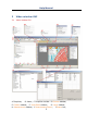
Help Manual 3 Image window GUI 3.
Help Manual 3.2 How to close the Image window? 1.
Help Manual box and enter the file name in the File name edit box. Click Save to save the captured image with the specified directory and file name, or Cancel to close the Save As dialog and return to Image window. Clicking No on the ToupView dialog will close the file immediately with no changes and no warning or Cancel on the ToupView dialog will cancel the Close command and return to Image window. Note: 3). Choosing Windows>Close All command can also close the tabbed Image window.
Help Manual 4 UI toolbar When the camera is started or the image is opened, most of the icons on the toolbar will be available for the quick setup of the Video or Image characteristic.
Help Manual 5 Camera sidebar Camera sidebar is used for the control of ToupCam camera, it included 10 groups. The group can be expanded by clicking the group name or clicking the Down Arrow at the right of the group name. 5.1 Capture & Resolution group Snap: Continuously Snap images by clicking it; Record: Record Video stream in wmv/asf or avi format; Live: Set the Video resolution; Snap: Set the Snap resolution for use in the image capture process. 5.2 Exposure & Gain group 1.
Help Manual 5.4 Color Adjustment group 1. Hue: Adjusts the Hue of the image. Drag the slider to the right to increase or drag to the left to decrease hue; 2. Saturation: Adjusts the Saturation of the image. Drag the slider to the right to increase or drag to the left to decrease saturation; 3. Brightness: Adjusts the image Brightness. Drag the slider to the right to increase or drag to the left to decrease the image's brightness; 4. Contrast: Adjusts the image Contrast.
Help Manual 5. For DC power, no light fluctuation is existing and no compensation is needed. 5.9 Sampling group 1. Bin: Pixel binning refers to the method of combining (averaging) pixels of blocks of neighboring same color pixels; 2. Skip: Also called "Decimation", means that a certain amount of pixels is not read out but skipped (horizontally, vertically or in both axes). This reduces resolution of the resulting image but introduces subsampling artifacts. 5.10 Histogram group 1.
Help Manual 6 File 6.1 Open Image••• Choose File>Open Image••• Ctrl+O command to open an existing image file. Open Image••• can also be used to preview an image in small size, or to view its statistics and information without actually opening the image itself. These capabilities can be used to quickly locate a particular image. ToupView supports and can open many image formats. These are identified in the Files of type list box. You may also open an image file called ToupView File Type (*.
Help Manual listed (beneath Exit), the Open Image••• command must be used to open the file. Also, View>Browse can be used to view images under any selected directory. Brief information is given in View>Browse menu. File name: From this list box, select the name of the file want to open. Either the type of the file name (with its entire path, if it is not in the current folder), or selecting Files of type to obtain a list of file names.
Help Manual Preview: Click this button to preview image in small size. In preview mode, statistics and information about the image (i.e. image Width, Height and image location) will be displayed. The default is no Preview. 6.2 Open Video••• 1. Choose File>Open Video••• command to open an existing Video file; 2. Select the name of the file you want to open. If the file does not appear, select the option for showing all files from the Files of Type in the list box. The Video file type can be *.wmv*;*.
Help Manual 6.3 Camera List ToupView will detect all of the cameras that your computer has installed (Here, it is UCMOS03100KPA, a 3.1M pixel CMOS camera) and will append all the camera names as submenu to File>Camera List menu (Here, the submenu name is “UCMOS03100KPA”). Choosing File>Camera List> UCMOS03100KPA will create a Video window and begin to start the Video stream. Your Video window will be associated with the name of “Video [UCMOS03100KPA]” (i.e.
Help Manual provide a Source Manager and Twain Data Source to work with ToupView. Select the active device for Twain: Acquire••• from all devices available in the device list box which are enumerated by the application. One must install the Twain Device hardware and its driver first. See the documentations provided by the device manufacturer for the installation instructions.
Help Manual 3. Plug the cameras UHCCD01400KPA (USB2.0) into the computer; 4. Start ToupView; 5. Choose File>Twain:Select Device••• command to select the device UHCCD01400KPA from the Select Source dialog; 6. Choose File>Twain:Acquire••• command. There should be a dialog box like below: In this dialog, Video Resolution can be selected (dropdown list if it has). The Video Source Property••• can be set by clicking the Setting••• button. Click the Capture button to capture an image.
Help Manual active in its window. If the image is in an untitled window, ToupView will issue the File>Save As••• dialog. The File>Save command can be used to save the most recent changes to disk. It is often performed as a precautionary measure during lengthy or involved processes to reduce the amount of reprocessing that might be required in the event of a system failure or operational error.
Help Manual Save as type: In this list box, select the format in which the image wants to be saved. Save As is also used to convert a single image from one format to another. For example, if a TIFF file needs to convert to PCX format, open the TIFF image first, then choose Save As command with the PCX format option to save it to a new file. The Save As command has several important uses beyond simply storing an image to a new file name. Click Option to select the different parameters to encode the file.
Help Manual Optimize Huffman codes The default is unchecked. Smoothing The values range between 0 and 100. Default value: 0. Save these setting as When saving a file, the current settings will be saved as defaults defaults for the next file save operation. For Portable Network Graphics (*.png), Option has the following items: Interlaced The default is unchecked. Save these setting as When saving a file, the current settings will be saved as defaults defaults for the next file save operation.
Help Manual compression. Predictor compression offers improved compression by rearranging floating point values, and works with both LZW and ZIP compression. If choosing Compressions as "JPEG", the Image quality Image quality can be adjusted by the slider bar. The values range between 0 and 100. Default value: 75. Save these setting defaults as When saving a file, the current settings will be saved as defaults for the next file save operation. For Compuserve GIF (*.gif) PCX(*.pcx) Targa(*.
Help Manual directory when startup under the Privacy item. 6.8 Batch Save••• If many files have been snapped and needed to be saved. Choose File>Save As••• command to realize the save target. But this will be time-consuming. The Batch Save••• command runs File>Save As••• command with the name automatically specified according to the paradigm specified in the Batch Save dialog To start File>Batch Save••• command, you have to 1. Start the camera; 2. Snap at least an image first; 3.
Help Manual (can be BMP, JPG, PNG, TIF). Click Option button to select the different parameters to encode the file (For BMP format, the Option will be disabled. See File>Save As••• menu about the details of the format encoding methods); Sample: The final file name is shown at the right of the Sample: label for reference. 4, If everything was finished, click OK button to begin the file batch save process or Cancel to cancel the File>Batch Save••• command and return to the application area.
Help Manual 6.11 Print Preview••• Ctrl+Shift+P Choose Print Preview command to see the real-time effect of the printer without actually printing it out. 6.12 Print••• Ctrl+P Choose File>Print command to print one or more copies of the current image to the selected output device. The ToupView File>Print command lets one take full advantage of the printer's capabilities.
Help Manual 6.14 Exit Choosing File>Exit command will close all of the active images and remove their windows from the screen. After all of the images are closed, ToupView will end itself. Note: If an image has been modified before attempting to Exit it, ToupView will issue a warning to ask if user want to save the image or not first.
Help Manual 7 Edit 7.1 Undo/Redo Ctrl+Z Most of the operations in ToupView can be undone. Alternatively, one can restore all or part of an image to its last saved version. The basic Undo process is: 1. Choose Open Image••• to open an image; 2. Choosing Image>Adjust>Auto Level, then Edit>Undo will be enabled; 3. Choosing Edit>Undo command will cancel the Image>Auto Level operation and return the image to its initial opened state.
Help Manual This command will move the current displayed image to the next step listed in the Undo/Redo sidebar (If it is not in the final step). Forward Demo 1. Open an image, choose Image>Adjust>Auto Level, choose Image>Adjust>Invert and check Current on Index 1(Open Operation). Now we continue the Edit>Forward demo. Since it is in Index 1, Edit>Backward is disabled and Edit>Forward is enabled. The status is shown in Fig.1. 2. Choosing Edit>Forward, the image and the Index will advance forward to Fig.2.
Help Manual This command will move the current displayed image to the previous Index listed in the Undo/Redo sidebar (If it is not in the "Open" status). Backward Demo 1. Choose Open Image••• to open an image; 2. Choose Image>Adjust>Auto Level command; 3. Choose Image>Adjust>Invert command The final image is shown in Index 3. Since it is in the final step (Fig.3), the Edit>Backward will be enabled; 4. Choosing Edit>Backward, the image and the Index will return to Index 2 as shown in Fig 2.
Help Manual 7.4 Cut Ctrl+X The Edit>Cut menu will be enabled only when an object or some objects on the Layer is or are selected. See Measurements>Object Select or Edit>Select All menus about how to select Layer objects for Edit>Cut operations Choose Edit>Cut command to copy the selected Measurement objects to the clipboard and delete the selected objects on the image. Any data already exist on the clipboard will be replaced.
Help Manual 4. Move the mouse until the cursor becomes , this means the cursor is now right on the Object. Clicking it will highlight and select the Measurements Object; 5. Optional 1: Continue to move the mouse until the cursor becomes , this means the cursor is now right on another object. Clicking it with SHIFT+left mouse button and the second object will be selected and highlighted; 6. Optional 2: (1) Move the cursor over the image, click down the left mouse button.
Help Manual command and the Layer menu in Sec.13 for details. 7.6 Paste Ctrl+V Choose Edit>Paste command to put objects from the clipboard onto the active image's Measurement Layer. One can also choose Edit>Paste command to transfer a layer's Measurement objects from one image window's Measurement Layer to another image's Measurement Layer. Note: 1) Before executing the Edit>Paste command, valid Measurement object must have been copied into the clipboard (see the Edit>Copy command).
Help Manual toolbar will keep it down). After the area is selected, the Edit>Copy button (or menu) will be enabled and then the selected area can copy to the clipboard for further application. Note: Only when the Current is checked on the Background item, the Edit>Copy command can copy the selected to the clipboard. 7.8 Select All Ctrl+A Edit>Select All command is used to select the Current object(s) (Background image or all of the Layer objects) at a time. 7.8.
Help Manual were not previously selected. Click Edit>Invert Selection to inverse selection. 7.11 Delete File Delete This command is for Browse window only. You can Delete or remove one or more files from the Browse window. The steps are as follows: 1. Select one or more files by a) Clicking the displayed file icons; 2) Clicking the files with CTRL+left mouse button; 3) Dragging the mouse to draw a dotted line rectangle across the files you wish to delete; 2.
Help Manual 8 View 8.1 Browse Ctrl+B 8.1.1Open the Browse window 1. Choose View>Browse from the View menu or click the Browse toolbar button to browse images on the hard disk; 2. Click Folders sidebar to activate it and double-clicking the listed directory in the Folders sidebar will create the Browse window. After creating the Browse window, ToupView will display a Browse window that looks like windows explorer.
Help Manual View>Sort>Sort by Height View>Sort>Forward View>Sort>Reverse View>Icon>Large Icons View>Icon>Small Icons View>Refresh for details Note: The Browse can be used to perform tasks such as creating new folders, renaming, moving, and deleting files. Individual file information and import data from digital cameras can also be displayed. Double-clicking the left mouse button on the icon will open the image as an active image in full size. See ToupView’s image window UI for more details. 8.
Help Manual This command is for the Browse window only. Sort the image files in order of the Forward mode (i.e. 1,2,3,4) in the Browse window. 8.8 Sort>Reverse This command is for the Browse window only. Sort the image files in order of the Reverse mode (i.e. 4,3,2,1) in the Browse window. The Sort settings are saved until they are changed. For example, if you sort images in the Browse window according to the Type, the images will remain sorted according to Type until the Sort settings are changed. 8.
Help Manual Choose Refresh to refresh the image files in the Browse window. 8.12 Measurement Sheet When choosing View>Measurement Sheet command, the Measurement Sheet shows the object's possible features, such as Name, Center Point, Radius, Area, Perimeter, Angle, Start Point, and End Point overlaid on the extra layer. Clicking the right mouse button on the Measurement Sheet••• and the above context menus or context submenus will be brought up on the Measurement Sheet•••: 8.12.
Help Manual to Microsoft Excel with the Measurement object and image together. The objects' parameters in the Measurement Sheet will also be exported as a table on the same frame with the image. Note: This menu will be enabled only when there are Measurement objects over the Background Layer. 8.12.5 Auto Highlight When this menu is checked, clicking the row in the Measurement Sheet will Highlight the corresponding Measurement object over the Background Layer.
Help Manual 1. To modify the Measurement Sheet’s item order. Select an item, and click the Up or Down button to move the selected item forward or backward; 2. Checking/Unchecking the item will show/hide the item in the Measurement Sheet; 3. Clicking Default will return to the ToupView's default settings. 8.13 Sidebar There are 5 sidebars for the ToupView frame window. They are Camera sidebar, Folder sidebar, Undo/Redo sidebar, Layer sidebar and Measurement sidebar. 8.13.
Help Manual CD: Indicating which step is the Current one displayed in the image window; CE: Step Index; DA: Layer sidebar; CF: Operation name. DB: Make a New layer; DD: Set the Current layer; DC: Remove a layer; DE: Show/Hide a layer; DF: Rename a layer; DG: Visibility control of the layer items; DH: The Current active layer for operations; DI: Layer Name; the image layer is always named as “Background” See details about the Layer sidebar in Layer Operations.
Help Manual context menu as shown below: This is the basic window explorer menu and will be explain it in this manual. 8.13.4 Sidebar>Undo/Redo Undo/Redo sidebar is used to Undo/Redo the Image and Process menus’ image operations. 8.13.5 Sidebar>Layer Layer sidebar is used for the management of Layer operations. This operations including making a New Layer, Removing a Layer or Renaming a Layer and Layer visibility controlling et al. 8.13.
Help Manual on the top of the Vertical Ruler and on the left of the Horizontal Ruler as shown below: Move the mouse to the Down Arrow will show horizontal drag icons. Drag the Down Arrow along the Horizontal Ruler to where ever you want. When it is dragged over the image, there will be a Vertical line displayed to let you judge where to release this line on the image. You can drag any lines to overlay them on the image. Move the mouse to the Right Arrow will show vertical drag icons.
Help Manual 8.14.4 Grids>Remove All Grids Remove all of the Manually Grids or Auto Grids overlaid on the image. 8.14.5 Settings••• Choosing this menu will show the Preference dialog. Click Ruler and Grids page. In this page, one can select Ruler Color, Cursor Color, Grid Style, Line Style, and Line Color. Click OK to accept the settings or Cancel to return to the application area and cancel the settings. 8.15 Best Fit Choose Best Fit to automatically resize the Video or Image to fit in the window.
Help Manual positioning the Video/Image within the window. Checking this menu will change the cursor to and the button on the Toolbar will be checked. Then keep down the mouse button to drag the region of interest on the Video/Image to any location in the Video/Image window. Note: If the Video/Image display area is smaller than the window size. The track will be ineffective. 8.18 Properties If an image file listed in the Browse is highlighted.
Help Manual The file Properties dialog including 4 pages. They are General, Security, Details and Previous Versions pages. They may depend on the operating system and we do not discuss it in this help.
Help Manual 9 Setup 9.1 Start/Pause If the Video window is paused, one can continue the Video process by choosing Start/Pause menu. If the window is running, one can choose Start/Pause command to pause the Video and choose Start/Pause command again to start the Video. 9.2 Full Screen Choose Full Screen to display the Video window in full screen style. Press ESC to enter Full Screen mode. Press ESC again will return to the default Video window.
Help Manual Still Image Capture Whether or not the camera supports Still Image Capture. Still Image Capture is used for high resolution camera to capture an image with a different resolution from the video. This feature is mainly used to capture high resolution image under low resolution video to compromise the frame speed and the image resolution. Display Width The Video window width. Display Height The Video window height. Video Width The actual Video window video width.
Help Manual together. Their Colors can be defined separately. Clicking OK and the Scale, Magnification and Date, and Clarity Factor will be overlaid on the Video window. The Clarity Factor can tell if the sample is in good focused state. The larger the Clarity Factor, the better the sample focused. Note: To enable the Scale bar, the Magnification must be defined and selected at first. The Unit can be any unit except Pixel. There are two methods to set the Unit, they are: 1.
Help Manual Enter the Cross Width and Cross Height, Rectangle Width and Rectangle Height, x Offset and y Offset, in their specific fields. Click Color••• to define the Video Marker color. Click OK to end the Video Marker dialog and a Cross+Rectangle Marker will be overlaid over the image.
Help Manual overlaid on the Video window. The steps are: 1. Choose Capture>Capture Image or click to capture the micro ruler image as shown in Fig.1; 2. Choose Process>Binary••• command to binarize the image as shown in Fig.2; 3. Choose Image>Adjust>Invert command to invert the image and choose Image>Color Quantize••• command to convert the image into 24 bits as in Fig.3. Choose File>Save As••• command to save the image in 24 bit BMP format; Fig.1 Captured Micro Ruler Fig.
Help Manual Fig.5 Video Window with Video Watermark overlaid 9.6 Move Watermark 9.6.1Move to••• If there is Watermark overlaid on the Video, this menu will be enabled. Choosing Setup>Watermark••• command will bring up a Move dialog. Where one can enter the X: and Y: offset value in their fields for the desired pixel move distances. 9.6.2 Move to zero If the Watermark was moved, this menu will be enabled. Choosing this menu will move the Video Watermark to its original coordinates (0,0). 9.
Help Manual 9.7.2Rotate to zero If the Video Watermark was rotated, the Rotate to zero menu will be enabled. Choosing this menu will rotate the Video Watermark to zero degree. 9.8 Gray Calibration••• This function can make specified area image brightness a desired value among various scenarios, achieving the continuity requirement of the observation. The Gray Calibration steps are summarized as follows: 1.
Help Manual 9.9 Manual Fusion••• Make sure that the ToupView package and UCMOS or UHCCD camera are correctly installed. Turn on the microscope's light. 1. Run ToupView and start the camera; 2. Choosing Setup>Manual Fusion••• command or clicking on the toolbar will bring up a dialog called “Manual Fusion”; 3. Use the microscope coarse or fine focus knobs to move the sample stage up and down, in order to find the positions where the clearest regions of the whole sample can be seen on the Video window; 4.
Help Manual 2. Clicking Capture button will capture the current image into the image fusion list; 3. Repeating steps 1-4 until there are enough images; 4. Clicking the Fusion button will start image fusion. Waiting for some time and a fantastic fusion result will be displayed in a new Image window; 9.10 Video Source Property••• This menu will be displayed and enabled only when the camera that supports directshow interface is started.
Help Manual directshow interface is started. The ToupView Video Stream Format••• configuration dialog is shown below: One can change the video format mode, frame rate, color space, compression options and so on. Here, we only have the Video Size to select. Selecting the desired one and clicking OK. This will give you a selected Video Size.
Help Manual It has 3264*2448, 1600*1200, and 800*600 resolutions. Select the desired one and press OK to accept the selection, or Cancel to ignore the current selection. Click Apply to apply the selection. One can find if the device supports Still Image Capture or not by choosing Setup>View Property•••. If the Still Image Capture's Value is Y in the View Property••• dialog, this means that the camera supports the Still Image Capture operation.
Help Manual 10 Capture 10.1 Capture Image F8 During the Video preview, you can always choose Capture>Image Capture command to capture the Video image. After the image is captured, the captured image will be the current active window. The Capture>Capture Image menu will be disabled. If you wish to capture image again, click the Video window title to activate the Video window and the Capture>Capture Image menu will be enabled again.
Help Manual Toutle Images: Checking Total Images will enable its edit box. You can enter the Total Images (1-9999) to be captured. ToupView will stop the Time-lapse capture process automatically when the Total Images are reached. If Total Images is unchecked, ToupView will capture the images continuously until you choose Capture>Stop Time-lapse (Auto capture) command to stop the Time-lapse capture. Click OK to begin the Time-lapse capture, or Cancel to cancel the Start Time-Lapse(Auto Capture) ••• command.
Help Manual 2. Enter the video file name under 1.Set the name for the captured video file field and click the Browse… button under 2 Select the directory for the video file item to locate the video file directory. Click Back to return to the Video Format dialog, or Next to the next step; 3. An Encoder dialog will be brought up. Here you can select the Encoder format, set the Bitrat(Kbps)(256-16384), Quality (1-100) and Key Frames Spacing (1-30).
Help Manual 4. A dialog called Display Information will be brought up. Here you can enter Title, Author, Copyright and Description to their fields. Click Back to return to the Encoder dialog, or Next to the next step; 4. A dialog called Start to Capture will be brought up. Here you can check Time Limit (Minutes 1-1440) and enter recording time (If checked); Input Time-lapse(1-100). There is a Summary text to display what you have been defined.
Help Manual 5. After the Video capture is started. The sidebar will become button on the Camera . Clicking will stop the capture process, otherwise ,it will stop untill the Time Limit is reached. After the Video capture process is finished. The on the Camera sidebar will become for the future Record process; 6. You can choose File>Open Video••• command to display the captured video file in the Video window; 7. Clicking on the Video window with you right mouse button will bring up a context menu.
Help Manual 11 Image 11.1 Mode 11.1.1 Color Quantize••• The Color Quantize••• command is widely used to change the image bit. ToupView supports the mutual changes among 1, 4, 8, and 24 bit images. When the dialog is opened, the default checked color bit is the image's color bit. Check the desired bit and click OK to end the command. The image will converted to the selected color bits. 11.1.
Help Manual Curve: Drag the Curve until the image looks satisfactory. Pencil: Check the pencil button at the bottom of the dialog, and drag it to draw a new arbitrary Curve. Channel: To adjust the color balance of the image, check the channel(R, G or B) from the Channel button. Check the white button to select RGB channels at the same time, which is located on the left of the R (Red), G (Green) and B (Blue) buttons. 11.2.
Help Manual Auto Level gives good results when an image with an average distribution of pixel values needs a simple contrast adjustment or when an image has an overall color cast. However, adjusting the Curves manually is more precise. See Auto Contrast for another auto adjust command. 11.2.3 Auto Contrast The Auto Contrast command automatically adjusts the overall contrast and mixture of colors in an RGB image.
Help Manual Histogram Equalization is a kind of histogram process. The histogram can reflect the statistical information for the R, G, and B of the pixels of the original image. The algorithm calculates each separately, equalizes the R, G, and B of the points linearly, and reassigns them 11.2.5 Brightness/Contrast••• The Brightness/Contrast••• command offers simple adjustments to the tonal range of an image. This command makes the same adjustment to every pixel in the image.
Help Manual and a B value of 50. When the values of all three components are equal, the result is a shade of neutral gray. When the value of all components is 255, the result is pure white; when the value is 0, pure black. RGB images use three channels to reproduce up to 16.7 million colors on-screen. In addition to being the default mode for new ToupView images, the RGB mode is used by computer monitors to display colors.
Help Manual Intensity is the relative lightness or darkness of the color, usually measured as a percentage from 0% (black) to 100% (white). The HLS model is very similar to the HLS color model. The main difference between them is the calculation used to produce the brightness value. In the HLS HLS model, a pixel's brightness (L) is derived from its three (R, G and B) color values. In the HLS model, a pixel's brightness (L) is determined by the minimum and maximum values of its three color values.
Help Manual 11.2.8 Gamma••• Gamma measures the brightness of midtone values produced by a device (often a monitor). A higher gamma value yields an overall darker image. Preview: Check this button to display the real-time effects when one changes the slider bar’s position. Gamma: Dragging the slider bar to the left decreases the level, while moving it to the right increases the level. Values can range from 0 to 3.0. 11.2.
Help Manual For every pixel, if selecting Red color to extract, only information about the red channel will be kept, and Green and Blue information will be discarded. See Filter Color••• for another color operation. 11.2.11 Invert Choose Invert command to reverse the pixel values of the active image without going through the lookup table 11.3 Rotate Choose Rotate command to rotate the entire image. One has the following submenus: 11.3.1 90(CW) Rotate the image clockwise by a quarter-turn. 11.3.
Help Manual Degree: The degree that the image to be rotated. CW: Rotates the image clockwise. CCW: Rotates the image counterclockwise. Quality: One can select one of the three methods for the image rotation among Nearest Neighbor, Bilinear, and Bicubic. The default is Bilinear. 11.3.5 Flip Horizontal Reverses the image in the application area so that the top right corner of the original image is now the top left, and the top left corner of the original image is now the top right corner. 11.3.
Help Manual hold it down. 4. Drag the mouse over the part of the image to be kept, a dotted rectangle appears around the selection. 5. Optional 1: To move the rectangle a) Move the mouse over the selected area and when it becomes a move cursor, click and hold the left mouse button. b) Drag the selected area to the desired position. 6. Optional 2: To change the size of the rectangle a) Put the mouse cursor on one of the handles that appear on the edges of the selected area.
Help Manual Width and Height: When choosing Image Scale command; the dialog displays the dimensions of the original image in pixels. The Width and the Height can be set on the new image by adding or removing pixels. If Constrain Proportions is checked, the Width and Height will stay proportionate to each other. If Constrain Proportions is unchecked, the Width and the Height can set independently, but this will distort the image. Reset: Reset the image Width and Height to the original ones.
Help Manual Choose Image>Histogram••• to open the Histogram dialog as shown below. Depending on the image’s color mode, choose R, G and B, or Luminosity to view a composite Histogram of all the channels. If the image is RGB true color, choose Luminosity to display a Histogram representing the luminance or intensity values of the composite channel. If the image is RGB true color, choose R, G and B to display a composite Histogram of the individual color channels in color.
Help Manual Level: Displays the intensity level of the area underneath the pointer. Count: Shows the total number of pixels corresponding to the intensity level underneath the pointer. Percentile: Displays the cumulative number of pixels at or below the level underneath the pointer. This value is expressed as a percentage of all of the pixels in the image, from 0% at the far left to 100% at the far right. 11.7 Resolution••• Choose this command to set the image Resolution to calibrate the spatial scale.
Help Manual Position can be Top Left, Top Right, Bottom Left or Bottom Right. The scale bar can be in Auto or Fixed mode. The Font Size and Font Weight can be chose.
Help Manual 12 Process 12.1 Filter••• Shift+F Choose Filter command to apply one of ToupView's numerous Filters to the active image. If one is not familiar with the process and effects of filtering, some discussions about spatial filtering should be reviewed. ToupView provides an extensive set of convolution and no convolution (morphological) Filters. One can also create custom filter kernels and apply them with the Filter commands. Choosing Filter command will open the Filter dialog.
Help Manual Gauss Check this filter to soften an image by eliminating high-frequency information using a Gauss function. This has the effect of blurring sharp edges. The operation of the Gauss filter is similar to the Low Pass filter, but it degrades the image less than the Low Pass filter. High Gauss Check this filter to enhance fine details. This operation is similar to the unsharp masking technique (see the Sharpen filter), but it introduces less noise into the image.
Help Manual Passes Set the filter applied times on the image. When a filter is applied multiple times, its effect is amplified by each pass. An image that has been softened by one pass of the Low Pass filter will be softened further by a second pass. Strength Enter an applied value from 1-10 that reflects how much of the filtering effect on the image. A value of 10 specifies the full strength (100%) of the filtered result applied to each pixel. Values less than 10 cut the full weight of the filter.
Help Manual maximize the contrast between the brightest and darkest pixels in the local window region. Linear This option distributes the histogram linearly across the intensity scale. This function produces a high contrast image with the highest possible dynamic range. Logarithmic This option concentrates the histogram at the low end of the scale. This function produces a high contrast image with little dynamic image. It will tend to darken the image overall.
Help Manual Horizontal Check this filter to detect and emphasize horizontal edges. Vertical Check this filter to detect and emphasize vertical edges. Options: 1. If one of the Edge filters has been checked, the options will relate to kernel size and filtering strength. The following options will be displayed: 3x3 Check 3x3 kernels to produce a more subtle filtering effect. 5x5 Check 5x5 kernels to produce a moderate filtering effect. 7x7 Check 7x7 kernels to produce a more extreme filtering effect.
Help Manual Erode Check this morphological filter if one wants to modify the size of objects in the image. The Erode filter erodes the edges of bright objects and enlarges the edges of dark ones. Dilate Check this morphological filter if one wants to modify the size of objects in the image. The Dilation filter dilates bright objects and erodes dark ones. Open Check this morphological filter if one wants to modify the shape of objects in the image.
Help Manual Thinning filter will not operate upon True Color images. If one wants to thin a True Color image, he must first convert it to Gray Scale. Distance The distance filter is used to show the distances of pixels within blobs to the outer boundaries of those blobs. After applying the distance filter, the background will be black (i.e. pixels with value 0). Only the area within the blobs will have non-zero values (will be white).
Help Manual better than square configurations. 2. If the Tophat, Well, or Gradient filter is selected, the options will relate to kernel size and shape. The following options will be presented: 3x3 Check to use the 3x3 square kernel configurations. 5x5 Check to use the 5x5 square kernel configurations. 7x7 Check to use the 7x7 square kernel configurations. 3. If Watershed, Thinning, or Distance filter is checked, the options will relate to the threshold.
Help Manual operation of these filtering options, they must not be deleted or renamed. Filter type Edit••• Check to modify the kernel for a selected Filter type, either Convolution or Morphological filters. Check to modify the selected filter kernel using the Edit Kernel dialog. This list box contains the name of the selected kernel file. If Name••• one wants to save the modified kernel file to the same file, leave it as it is. If one wants to save the file to a new location, enter the new filename here.
Help Manual The choices in this group box will vary depending upon the kind of Options selected filter. 12.2 Range••• Shift+R The Range command allows set the intensity levels of the image to increase the contrast and enhance the display in low-light situations. Choose Range command to open the Range dialog. Two vertical markers show the upper and lower limits of the intensity levels. These markers can be moved with mouse through the drag and drop process.
Help Manual identified by Segmentation (classes) can either be removed from or kept in the image, while discarding the remainder of the image. Therefore, this process can be used for separating items or objects of interest from the "background noise" that normally occurs in most acquired images. The process of identifying colors is the key to the operation of Segmentation.
Help Manual threshold, or change the number in the top left corner of the dialog to change it. Click the "Best Fit" button to apply the auto threshold process to the image. It uses an automatic threshold to make the image Binary. 12.5 Emboss••• Shift+E Emboss is a kind of artistic process. The process can make the image look like an empaistic image. The Preview button allows previewing the image before creating it. The process supplies 3 kinds of convolutions including Gradient, Different, and Prewitt.
Help Manual palette,). It simply associates a Pseudo Color palette with the image that interprets the gray-level values in the image as color. Pseudo Colored images are very similar in structure to palette class images, but they differ in a couple of important ways. First, the pixels' values in a Pseudo Colored image actually represent continuous-tone intensity information, whereas a palette image's pixels carry no intensity significance.
Help Manual 12.8 Line Profile••• Choose Line Profile••• command to illustrate how pixels along a selected line are distributed by graphing the number of pixels at each color intensity level.
Help Manual 12.9 Diffuse••• Shift+D Diffuse is a kind of artistic process. It can diffuse the image. Users can adjust the parameter in the dialog to control the degree of the diffusion. Preview: Check it to display the real-time effect when drag the slider bar. 12.10 Granulate••• Shift+G Granulate is a process that can make the image fuzzy. One can adjust the parameter in the dialog to control the degree of the fuzziness. 12.
Help Manual Available Images: Images opened with Toupview. Add>>: Add the opened images to the Selected Images list view Add All>> Add all the opened images to the Selected Images list view Remove: Select the images and remove them from the Selected Images list view. Clear: Remove all the images from the Selected Images list view.
Help Manual 12.12 Fusion••• Similar to the dynamic multi-focus image fusion with the live video stream, static Fusion is a very useful tool to generate a clear image by combining a sequence of previously captured multi-focus images. Choosing Process>Fusion••• command, the following dialog will be brought up (assume 01.jpg 02.jpg ••• 15.
Help Manual Clicking Add all button will add all images in the Open list box into the Selected list box. If images in the Selected list box is highlighted, the Delete button will be enabled. Click the Delete button, the highlighted images in the Selected list box will be removed. Clicking Clear button will remove all the images in the Selected list box, including the unselected ones.
Help Manual 12.13 Color Composite••• Use the Color Composite dialog box to create and configure color composites using black and white source images. You can access the Color Composite dialog box through the Color Composite menu item from the Process menu. You can combine gray-scale images into a color composite. Any group of gray-scale images that are of the same size can be mixed in a color composite. Images of 8-, 12-, 16-bit integer or floating point format are combined into a 24-bit color composite.
Help Manual Source Images: The Source Images combo box displays the images available for color mixing. The Source Image list is initially filled with a list of the gray scale images that are currently open. The size of the color composite is determined by the first input image selected. Once this is entered, the list is filtered to contain only images of the same size as the initial selection. Add: Click the Add button to add an image to the mix.
Help Manual Directly select a color by: 1) Dragging the Color Value Slider to the desired color on the Color Bar (range of 0 to 359°): or 2) Clicking the appropriate Color button on the Color Palette. The Color Bar represents Color degrees in the standard color wheel representation, and the Color Palette contains a subset of possible Colors (pure red, green, blue, cyan, magenta, and white): or 3) Select a dye in the dye list, and click the Select Dye button.
Help Manual If Color Value Slider is the selected (highlighted) selected control, then you can also control the slider with keyboard strokes: Use the left/right arrow <-> or <->keys to move the slider incrementally. Press the and to move the slider in “chunk” sections along the Color Bar. Use the and keys to move the slider to the beginning and end of the Color Bar.
Help Manual Registration: Registration allows you to correct for mis-registrations of images caused by filter-induced optical shifts. Use the directional keys to shift the selected image in the x- and/or y- direction, with respect to the rest of the input images. One click moves that channel one pixel in the direction indicated. Blank areas are filled with black. The key labeled “0,0” will re-center the selected image.
Help Manual Background allows the other inputs to be displayed “in front of” the background inputs, minimizing color mixing. For example, ToupView can display a red dot on a blue background without turning the dot to magenta. Selecting None causes all images to be equally mixed. New: Click on the New button to discard the current color composite image, and start over. The Source Images combo box will reset to include all gray scale images (including floating point images).
Help Manual 13 Layer 13.1 About Layer ToupView Layer is like sheets of stacked acetate. You can see through transparent areas of a Layer to the Layers below. You add a Layer to position the image content on the Layer, like sliding a sheet of acetate in a stack. You can also hide/show a layer to make content visible.
Help Manual A: Make a New layer; B: Remove a layer; C: Set the Current layer; D: Show/Hide a layer; E:Rename a layer; F: Auto hide the Layer sidebar; G: Right mouse button context menu for the Background layer; H: Right mouse button context menu for the Current not checked layer; I: Right mouse button context menu for the Current checked layer; J Right mouse button context menu in the blank area; Note: 1. Only one layer can be checked as Current Layer.
Help Manual 13.6 New••• Setup a new layer. After the new layer is setup, it will be added to the end of the Layer sidebar’s list items and the Visible and Current will be checked. 13.7 Remove••• Remove the non-current Layer. Note: the Background and Current Layer cannot be removed. 13.8 Current••• Set the selected layer as the Current Layer. User then can edit the object on the Current Layer or added new object on the Current Layer. 13.9 Show/Hide••• Set the non-current Layer visible or invisible.
Help Manual 14 Measurements Measurements menu is mainly used for the image measurement application. With this menu items, you can measure the image with many geometrical shape at ease. We use Layer technique to perform the measurement operations. This will never damage the image pixels. The Measurements menus and its submenus are shown below. About the Layer technique, please check the Layer menu and Layer sidebar in Sec.13.
Help Manual After the Measurement is done on the specific layer, choose this menu to select the objects. 1. The object can be selected by clicking on it; 2. Select a group of objects by including them in a rectangular area with Object Select command or by press down the Shift key and clicking the object with left mouse button until all the desired objects are selected.
Help Manual Here you can edit the corresponding object parameters to modify its properties; 2) The Appearance, Coordinates on Measurement sidebar will be enabled only when a single object is selected. The Calculation will be effective for a single selected object or more selected objects. Its calculated items will depend on the selected objects type (The type could be the same or could be different). 14.3 Point Move mouse to the point; click the left mouse to mark it.
Help Manual 3. Move mouse to the 2nd point, click the left mouse to mark it again, a line with L1 and its length will be shown. Note: 1) To check or modify the parameters of the selected object, just select a single measurement object and the Measurement sidebar will be activated automatically. Here you can edit the corresponding object parameters to modify its properties; 2) The Appearance, Coordinates on Measurement sidebar will be enabled only when a single object is selected.
Help Manual Here you can edit the corresponding object parameters to modify its properties. 2) The Appearance, Coordinates on Measurement sidebar will be enabled only when a single object is selected. The Calculation will be effective for a single selected object or two selected objects. Its calculated output lists will depend on the two selected object type (The type could be the same or could be different one). 14.5 Parallel 1. Choose Measurements>Parallel command; 2.
Help Manual objects type (The type could be the same or could be different). 14.6 Vertical 14.6.1 Vertical>Four Points. 1. Move mouse and click its left button to mark the 1st point. 2. Move mouse and click its left button to mark the 2nd point. A line (the 1st line) connect these two point be overlaid on the image 3. Move mouse and click its left button to mark the 3rd point. 4. Move mouse again, one will find the 4th point is always restricted to perpendicular to the line of point 1 and point 2.
Help Manual 3. Move mouse and click its left button to mark the 3rd point. The 2nd line will be overlaid on the image which is perpendicular to the 1st one. Note: 1) To check or modify the parameters of the selected object, just select a single measurement object and the Measurement sidebar will be activated automatically.
Help Manual 14.8 RoundRect 1. Measure Arc object to determine the round size. Its size is 21.39X2=42.8; 2. Choose Options>Measurement•••, click Round Rectangle to set the Round to 43 and 43 respectively; 3. Move mouse to the 1st point; click its left mouse button to mark it; 4. Move mouse to the 2nd point, click its left mouse button to mark it, a round rectangle with Rr1 and its lengths of the two dimensions will be shown.
Help Manual coincide with the image shape. Note: 1) To check or modify the parameters of the selected object, just select a single measurement object and the Measurement sidebar will be activated automatically. Here you can edit the corresponding object parameters to modify its properties; 2) The Appearance, Coordinates on Measurement sidebar will be enabled only when a single object is selected. The Calculation will be effective for a single selected object or more selected objects.
Help Manual object or more selected objects. Its calculated items will depend on the selected objects type (The type could be the same or could be different). 14.10.2 Circle>Two Points Choose Measurements>Circle>Two Points to draw circle with Two Points method on the specified layer. Note: 1) To check or modify the parameters of the selected object, just select a single measurement object and the Measurement sidebar will be activated automatically.
Help Manual mouse button. Two radiuses with number and the units will be shown on the Annulus; Note: 1) To check or modify the parameters of the selected object, just select a single measurement object and the Measurement sidebar will be activated automatically. Here you can edit the corresponding object parameters to modify its properties; 2) The Appearance, Coordinates on Measurement sidebar will be enabled only when a single object is selected.
Help Manual measurement object and the Measurement sidebar will be activated automatically. Here you can edit the corresponding object parameters to modify its properties; 2) The Appearance, Coordinates on Measurement sidebar will be enabled only when a single object is selected. The Calculation will be effective for a single selected object or more selected objects. Its calculated items will depend on the selected objects type (The type could be the same or could be different). 14.13 Arc 1.
Help Manual 3. Move mouse to mark the 2nd point, a rectangle with dash line restrict the Text window size. After the mouse button is released, a dialog called Text will bring up for you to enter the Text and define the Text, Frame styles and adjust the Text positions. 4. Enter the text and click the right mouse button to end the Text object. Note: 1) To check or modify the parameters of the selected object, just select a single measurement object and the Measurement sidebar will be activated automatically.
Help Manual measurement object and the Measurement sidebar will be activated automatically. Here you can edit the corresponding object parameters to modify its properties; 2) The Appearance, Coordinates on Measurement sidebar will be enabled only when a single object is selected. The Calculation will be effective for a single selected object or more selected objects. Its calculated items will depend on the selected objects type (The type could be the same or could be different). 14.
Help Manual 15 Options 15.1 Preferences••• There are 7 pages for the Preference dialog. They are File, Plugin, Print, Ruler and Grids, Cursor, Capture and Misc pages. 15.1.1 One can File check a file Extension for the specified file Format and its Abbr.(abbreviation), to determine whether it will be displayed in the image Browse window or not. 15.1.2 Plugin The ToupView installed Plugins will be appended to the Plugin menu with the name specified in the plugin.XXX.
Help Manual command and clicking Plugin page as shown as below: Click the left mouse button on the item to highlight it, the Config button will be enabled (This function is supported by the supplier, if this function is not provided; the Config button will be disabled). The same is true for the About button. 15.1.
Help Manual %c Date and time representation appropriate for locale %d Day of month as decimal number (01 - 31) %H Hour in 24-hour format (00 - 23) %I Hour in 12-hour format (01 - 12) %j Day of year as decimal number (001 - 366) %m Month as decimal number (01 - 12) %M Minute as decimal number (00 - 59) %p Current local times A.M./P.M.
Help Manual 15.1.5 Cursor This command will set the mouse cursor for the Video and Image window operations. Select the Horizontal cross in: None (window default), Single (single line), Double(1 Pixel), Double(3 Pixels), Double(5 Pixels), Double(7 Pixels), and Double(9 Pixels) formats. Select the Vertical cursor in: None (window default), Single (single line), Double(1 Pixel), Double(3 Pixels), Double(5 Pixels), Double(7 Pixels), and Double(9 Pixels) formats. Single means single line.
Help Manual meaning. Select the cursor shape from Cross, Point, and Null. In the figure below, a cursor with Double horizontal and vertical lines with 9 Pixels cross (for the alignment application, the longer one) and the Cursor as a Cross was defined 15.1.6 Capture If one wish to capture an image with many Measurement objects overlaid on the Video window, the following settings should be defined first. 1.
Help Manual Watermark or Measurement objects overlaid on the image. 15.1.7 Misc The Misc page is mainly used for the control of the ToupView UI. It mainly includes: 1. ToupView’ special file format warning information; 2. Sidebars; 3. UI Style; 4. ToupView Windows Layout; 4. Language; 5. Privacy; setting et al. 15.
Help Manual This dialog has many subsections. They are: 15.2.1 General>General The General page allows one to select “The calculation results keep: X decimals”, X is between 1 to 6. Select the Label font size (between 5 and 15). Check or uncheck Dimensions with unit. If it is checked, the Dimension will be displayed together with the unit for the Measurement objects. If unchecked, only the Dimension will be displayed with the Measurement objects.
Help Manual objects on the Layer Measurement operation. Unit: The system unit defined by the ToupView. It cannot be deleted. Current: The Unit selected. Type: Type of unit. It can be System or User defined. Scale: Represents the ratio of "Meter by unit". For example, if the unit is µm, then "Meter by µm" should be 1000000, the Scale should be e+6; Add: One can also define his own Unit.
Help Manual Here, one can enter the unit Name and Symbol in their fields. Here, we enter a name called Decimeter and its Abbreviation is dm, its Scale for Meter by Decimeter is 10. Click OK to end the Add Unit operation, or Cancel to cancel the Add Unit operation. The final Length Unit list looks like the figure below: You can find the Type is named with User. This means that this Unit is not defined by the System, but by the User. 15.2.
Help Manual To modify the Measurement Sheet’s item order, click the item to highlight it, and the Up or Down button to move the selected item Up or Down; 2. Checking/Unchecking the item will show/hide the item in the Measurement Sheet; 3. Clicking Default will return to the ToupView's default settings. 15.2.5 Object>Point The Object>Point’s Appearance describes the point Size and point Color. The Size is between 2 and 16. Clicking the Color button's drop down arrow can select the point Color.
Help Manual it on General>General page’s Label with name will add a Prefix before the number for clarification. Unchecking it, the Label will never be displayed on any Measurement object. 15.2.6 Object>Line The Line page can set the Line Width, Line Color, Line Style, Arrow shape, and determine whether the objects are being labeled or not. The Label is for all the layer's Lines.
Help Manual should look like 1. Select the Magnification item, click Delete••• to delete the selected item; 2. Select the Magnification item, click the Up or Down button to modify the Magnification list order; 3. Click Clear All••• to delete all of the Magnification items; If one wishes to reuse the Magnification, a backup is needed first; 4. Click Export••• to back up the Magnification in a safe media. The file extension is “*.magn”; 5.
Help Manual middle of the microscope field and try to find the ruler clearly. Set the Unit to Pixel and the video Resolution to the maximum one (640X480 0.35M camera) and Zoom ratio to 100% (see ); 5. Choosing Options>Calibrate••• or clicking “ ” on the toolbar, a red line with pixels number and 0.000um length is overlaid on the video. At the same time, a dialog called Calibrate will be displayed over the Video window; 6.
Help Manual the Resolution will be calculated and displayed simultaneously in the Resolution field. 9. If everything is ok, click Ok to end the calibration. The Magnification 10X (This is the number you entered in the Magnification edit box) will be available in the Magnification dropdown list box on the Video window toolbar ; 10.
Help Manual 10. The selected Resolution can be saved for the image future Measurement operations. If the Measurements are performed on the video, the objects and Resolution can be saved in the image with ToupView File Foamat (*.tft) for the future applications; 11.The other microscope Magnification such as 4X, 40X,100X can also be defined just as the above steps.
Help Manual dialog box: The list includes any dye definitions found in the current location. When this feature is used to prompt for a specific dye, the list indicates the currently selected dye, or you may select a dye from the drop-down list. Name: This list includes all dye definitions found in the current dye file. You may select a different dye from the drop-down list, and all the remaining controls will be updated to show the characteristics of the new dye.
Help Manual New: Clicking New will setup a new dye, this will invoke a dialog called New Dye. Input your New Dye name and click Ok to end the dialog and click Cancel to cancel the input. This will return to the Edit Dye List again and the new name will be the default on in the Name list box. Try to set the Emissions wavelength, Excitation wavelength, Color for your new dye. Save: Click Save on Edit Dye List to save your dye selection Close: Click the Close button to end the Edit Dye List dialog: 15.
Help Manual 16 Windows 16.1 Close All Choosing Closes All command to close all of the pictures opened or captured inside ToupView frame. If you have made any modifications to the pictures or if you have captured some pictures from the camera, Choosing Close All will let you finish the saving operations quickly. If the above image windows exist, choosing Windows>Close All will bring up a Save Files dialog as below: 1.
Help Manual saving operations have been finished; 3. Clicking No on Save Files dialog will bring up the Save Files dialog again if the unprocessed file number is large then 1. If it is the final file, it will only bring up a TouView dialog as step 2. Click Yes to save the final file, or No to give up the file; 4. Clicking Yes to All on Save Files dialog will always bring up Save As dialog to let you enter the File name to save files one by one; 5.
Help Manual 17 Help 17.1 Help Contents Choose Help>Help Contents command to load ToupView help files. 17.2 About Display the related information about ToupView, including ToupView Version, Compatible, Built date and its developer’s www etc. Clicking on URL will direct you to the address of the camera supplier. If one has problem with the camera or ToupView, please feel free to contact your supplier. Levenhuk, Inc.