
User Guide
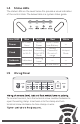

1.4 Status LEDs
The status LEDs on the Level Sense Pro provide a visual indication
of the control state. The below table is a system status guide.
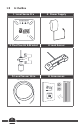
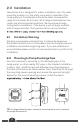
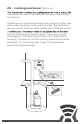
To connect sensors, turn the terminal screw counterclockwise to
open the wiring clamp. Insert wire into the clamp and turn
terminal screw clockwise to close clamp on wire.
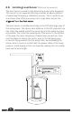
1.5 Wiring Panel
Color /LED Blue Yellow Red White
Power
AC Power
Good
No AC
Power
No AC Power
Low Battery
—
Cloud
Connected
to Wi-Fi
Flash:
Connecting
Solid: WPS
Mode
Wrong
Password
Or out-of-
range
Hotspot
Mode
Calibrate
Calibrated
Learning
Level
— —
Alarm
No Alarms
—
Active Alarm
—
RESET
DC
USER
LEVEL
SENSOR
FLOAT
SWITCH
LEAK
SENSOR
ALARM
NC COM NO
3