
Instruction Manual


Page 15 of 25
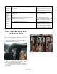
MAINTENANCE
HEAT EXCHANGERS
(Refer to manufactures specific IOM)
(ref. Valve listing)
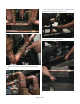
Shut down steam and supply water to heat exchanger by
turning off valves on the side to be flushed (59), and two
(41).
Open plugs (19) on the ends of the water pipes to the heat
exchanger.
Flush the heat exchanger per manufactures instructions.
Replace the plugs (19) after Teflon taping the threads to
insure no leakage.
Re-turn all valves to there run position.
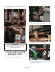
BLEND VALVES
(Refer to manufactures specific IOM)
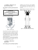
Figure 13 - MODEL B
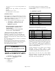
Service Parts For Model BO
Ref
No
Part No Description
3 9585L001 Seat, Bolted-In
4 1182 Sleeve
5 11132L050 Capscrew
6 11133 Lockwasher
7 1183 Element O-Ring, Buna-N
8 1096X(TEMP) Element Assembly
9 761 O-Ring
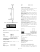
Figure 14 - MODEL C
Service Kit No. 9167X(Temp.) Standard Element
Ref
No
Qty Description Part No.
3 1 Element 1125X(A83723)
4 1 O-Ring 1205
5 1 O-Ring 277L145
6 1 O-Ring 11080L001
7 1 O-Ring 11079L001
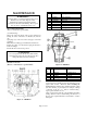
An element may be quickly checked by immersing it in an
agitated bath of water. Never use oil for checking the
element. Element number and nominal temperature setting
(last three numbers of part number) are stamped on flange
of element. At 10
o
F to 13
o
F above nominal setting ,
bypass port B should be closed.
Order new element by Part No. and Nominal Temperature
Setting, which is found on element flange. If these are not
known, send complete Model No. and Serial No. on Valve
Nameplate.
WARNING!
Warranty will be void if heat exchanger tubes are not
flushed every six months. Reports on this
maintenance by Heater Serial number must be
provided to Leslie after each flushing. These reports
are to be sent to sales@lesliecontrols.com
CAUTION!
Do not torque the U-bolts nuts more than 10 ft-lbs.
Over tightening of the nuts can cause the U-bolts to
collapse the shell of the heat exchanger.