
Install Instructions

INSTALLATION INSTRUCTIONS
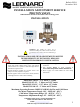
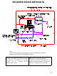
1. The Proton Unit MUST be piped according to Leonard Required Piping Method W (see page 10).
2. Mount valve body and plumb inlet and outlet connections. DO NOT introduce water to the valve
until completion of these instructions.
3. Mount Proton Control Box to desired location, within 6’ of Valve Body using suitable screws at 4-
hole locations on Control Box. Ensure all wiring connected to the Control Box is accessible.
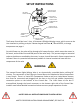
4.Remove compression fitting from rear-right side of the valve outlet. Slide RTD Probe #1 through the
compression fitting and insert into the rear-right side of the valve outlet. Tighten compression
fitting by hand, and then tighten just 1/8 to 1/4 turn. DO NOT overtighten fitting. See page 9 for
more detail.
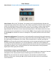
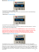
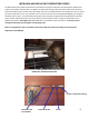
5.Connect and plug in, see pictures below, the 3-wire RTD Temperature Probe connector into the
bottom left connection point on the Control Box. Single-pin facing left side, press tab facing the
back, and press connector all the way in until firmly engaged and an audible “click” is heard.
6.Connect and plug in, see pictures below, press tab facing the back, the 4-wire Motor Connector into
the bottom center connection point on the Control Box. Press the connector all the way in until
firmly engaged and an audible “click” is heard.
7.Connect Barrel Connector to bottom right side of Control Box. This is 110Volt Power Supply.
8. Open all inlet and outlet check-stops and ball valves to pressurize Proton valve.
9. Plug power supply into 110V receptacle. GFCI receptacles are recommended. Installer to follow
local electrical codes.
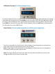
10. Powering Valve Control Box will cause the valve motor to initiate a FULL VALVE SWEEP (End to
End), indicating that the motor has traveled 900-1500 Steps. Please Record this initial Full Valve
Sweep Value __________ Following the FULL SWEEP, the valve is ready for use and the LED Screen
will display the following:
3
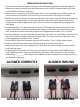
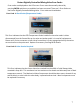
ALIGNED CORRECTLY
ALIGNED CORRECTLY
ALIGNED WRONG
ALIGNED WRONG