
Full Product Manual
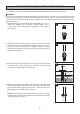
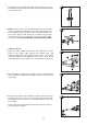
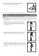

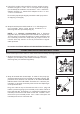

Table Of Contents

3
3.
4.
Air pressure in the tank must be 2 PSI lower than the
"cut-in" of the pressure switch.
4
Using PVC purple primer and PVC cement, attach a
section of 1 in. PVC pipe (not included) as needed to
connect the 1 in. male PVC adaptor on the discharge tee
to the 1 in. female PVC adaptor (not included) on the
tank tee. Attach another section of 1 in. PVC pipe as
needed to connect the other 1 in. female PVC adaptor on
the tank tee to the water system from the house.
NOTE: The pump (A) has a 30/50 PSI pressure switch,
which means the "cut-in" is 30 PSI; therefore, the tank
needs to be set to 28 PSI. To check the pressure in the
tank, use a tire pressure gauge (not included). If more
air is needed, add air to the tank with a tire pump or air
compressor. If less is needed, bleed out some air.
CAUTION! Never install a shut-off valve between the pump
and the tank, as this can cause excessive friction loss and
can damage the pressure switch and/or pump. If necessary,
only install a fully open gate valve (not included).
To prime, remove both:
a. The plug from the top of the discharge tee
(water will be filled in here), and;
b. The plug in front of the discharge tee on the pump
(this is to allow air to vent out while priming).
Fill the discharge tee with water until water overflows.
NOTE: It may take several minutes to fill the pipes and the
pump (A) completely.Wrap the discharge tee plug and priming
plug threads with thread tape and re-attach to the pump (A).
Tighten with wrench.
5.
5
6.
6
This pump (A) is pre-wired at 230 volts. If the power source
is 115 volts, remove the electrical housing cover. Flip the
switch to 115 volts. Replace the cover.
NOTE: All electrical work should be performed by a licensed
electrician.
10
A