
User Manual


EDS94TA10050xxxx EN 1.2 - 03/2010 L 13
9400 Technology applications | Table positioning
Parameter setting & configuration
Assignment of the I/O terminals
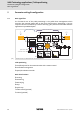
5.2 Assignment of the I/O terminals
5.2.1 Setpoint and control signals
The following tables contain the Lenze assignment of the analog and digital inputs for the
"Table positioning" technology application.
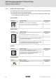
Analog inputs
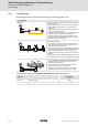
Digital inputs
Terminal X3 Signal (Lenze setting)
AI1-
AI1+
Selection for speed override
Speed/acceleration override
( 27)
AI2-
AI2+
Selection for acceleration override
Speed/acceleration override
( 27)
Terminal X5 Signal (Lenze setting)
DI1 Quick stop
• If DI1 is set to LOW level, the drive is decelerated to standstill within the deceleration
time set for the quick stop function independent of the setpoint selection.
• If the quick stop function is deactivated, the drive is led to the selected setpoint again via
the set acceleration time.
Quick stop
( 30)
DI2 Connection of reference switch/touch probe sensor
DI3 Connection of travel range limit switch positive/negative for basic function "Limiter
".
( 31)
• The inputs respond to the FALSE state (fail-safe).
DI4
DI5 Reset error
• By means of a LOW-HIGH edge an existing error status can be reset if the cause of the
fault is removed.
DI6 -
DI7 -
DI8 -
A1+
A1-
A1-
A1R
A2+
A2-
GI
RFR
DI1
DI2
DI3
DI4
DI5
DI6
DI7
DI8