
User Manual


EDS94TA10060xxxx EN 1.2 - 03/2010 L 71
9400 Technology applications | Positioning sequence control
Parameter setting & configuration
Parameterisable function blocks
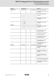
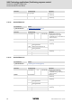
C04717/1...75
(subcode 1 ... 75 ≡ profile no. 1 ... 75)
TP window start position from VTPOS
• Reference to VTPOS table position
for defining the profile parameter
"TP window start position".
• For the position value "0", the
start position is the negative
travel range limit.
1 VTPOS position 1 (C04701/1)
2 VTPOS position 2 (C04701/2)
... ...
75 VTPOS position 75 (C04701/75)
C04718/1...75
(subcode 1 ... 75 ≡ profile no. 1 ... 75)
TP window end position from VTPOS
• Reference to VTPOS table position
for defining the profile parameter
"TP window end position".
• For the position value "0", the end
position is the positive travel
range limit.
1 VTPOS position 1 (C04701/1)
2 VTPOS position 2 (C04701/2)
... ...
75 VTPOS position 75 (C04701/75)
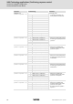
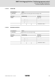
C04719/1...75
(subcode 1 ... 75 ≡ profile no. 1 ... 75)
Sequence profile with TP
• Sequence profile for touch probe
residual path positioning.
1 Profile no. 1
... ...
75 Profile no. 75
C04720/1...75
(subcode 1 ... 75 ≡ profile no. 1 ... 75)
Sequence profile without TP
• Sequence profile for profile
linkage.
0 No sequence profile
(End of profile linkage)
1 Profile no. 1
... ...
75 Profile no. 75
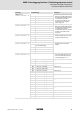
C04721/1...75
(subcode 1 ... 75 ≡ profile no. 1 ... 75)
Value is bit-coded: Touch probe configuration
• The touch probe channels to be
used are selected by setting the
corresponding bits to "1".
Bit 0 TP channel 1, rising edge Digital input 1
Bit 1 TP channel 1, falling edge
Bit 2 TP channel 2, rising edge Digital input 2
Bit 3 TP channel 2, falling edge
Bit 4 TP channel 3, rising edge Digital input 3
Bit 5 TP channel 3, falling edge
Bit 6 TP channel 4, rising edge Digital input 4
Bit 7 TP channel 4, falling edge
Bit 8 TP channel 5, rising edge Digital input 5
Bit 9 TP channel 5, falling edge
Bit 10 TP channel 6, rising edge Digital input 6
Bit 11 TP channel 6, falling edge
Bit 12 TP channel 7, rising edge Digital input 7
Bit 13 TP channel 7, falling edge
Bit 14 TP channel 8, rising edge Digital input 8
Bit 15 TP channel 8, falling edge
Bit 16 TP channel 9 Motor encoder zero pulse
Bit 18 TP channel 10 Load encoder zero pulse
Bit 20 TP channel 11 DFIN zero pulse
Bit 22 TP channel 12 DFOUT zero pulse
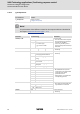
Parameter Possible settings Information