L-force Runtime Software Ä.
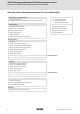
9400 Technology applications | Positioning sequence control Overview of the technical documentation for Servo Drives 9400 Overview of the technical documentation for Servo Drives 9400 Project planning, selecting & ordering Legend: 9400 Hardware Manual Printed documentation Catalogue / electronic catalogue (DSC - Drive Solution Catalogue) Online documentation (PDF/Engineer online help) Mounting & wiring Abbreviations used: MA 9400 StateLine/HighLine BA Operating Instructions MA for com
9400 Technology applications | Positioning sequence control Contents Contents 1 About this documentation . . . . . . . . . . . . . . . . . . . . . . . . . . . . . . . . . . . . . . . . . . . . . . . . . . . . . . . . . 6 1.1 Conventions used . . . . . . . . . . . . . . . . . . . . . . . . . . . . . . . . . . . . . . . . . . . . . . . . . . . . . . . . . . . . . . . 7 1.2 Definition of notes used . . . . . . . . . . . . . . . . . . . . . . . . . . . . . . . . . . . . . . . . . . . . . . . . . . . . .
9400 Technology applications | Positioning sequence control Contents 5 4 Parameter setting & configuration . . . . . . . . . . . . . . . . . . . . . . . . . . . . . . . . . . . . . . . . . . . . . . . . . . 28 5.1 Basic signal flow . . . . . . . . . . . . . . . . . . . . . . . . . . . . . . . . . . . . . . . . . . . . . . . . . . . . . . . . . . . . . . . . 28 5.2 Basic settings . . . . . . . . . . . . . . . . . . . . . . . . . . . . . . . . . . . . . . . . . . . . . . . . . . . . . . . . . . . . .
9400 Technology applications | Positioning sequence control Contents 5.14 Parameterisable function blocks . . . . . . . . . . . . . . . . . . . . . . . . . . . . . . . . . . . . . . . . . . . . . . . . . 5.14.1 ActualSpeedScaling . . . . . . . . . . . . . . . . . . . . . . . . . . . . . . . . . . . . . . . . . . . . . . . . . . . . . . 5.14.2 ApplicationError1 . . . . . . . . . . . . . . . . . . . . . . . . . . . . . . . . . . . . . . . . . . . . . . . . . . . . . . . . 5.14.3 ApplicationError2 . . . . . .
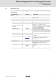
9400 Technology applications | Positioning sequence control About this documentation 1 About this documentation This documentation contains information about the technology application "Positioning sequence control" for the Servo Drives 9400 series. Note! This documentation supplements the mounting instructions supplied with the controller, the hardware manual and the software manual for the controller.
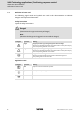
9400 Technology applications | Positioning sequence control About this documentation Conventions used 1.1 Conventions used This documentation uses the following conventions to distinguish between different types of information: Type of information Writing Examples/notes Numbers Decimal separator Point The decimal point is always used. Example: 1234.56 Text Program name »« Window pane Italics The Message window... / the Options dialog box... Control element Bold The OK button...
9400 Technology applications | Positioning sequence control About this documentation Definition of notes used 1.
400 Technology applications | Positioning sequence control Brief description 2 Brief description The technology application "Positioning sequence control" enables the drive to execute parameterisable travel profiles. The program sequence is defined by a sequence table. Functions Sequence control for several successive positioning steps with a break and stop functions and different auxiliary functions (e. g. deriving, counting, waiting).
9400 Technology applications | Positioning sequence control Introduction 3 Introduction Positioning means to move a workpiece/tool or a piece of material from a starting position n to a defined targeto. For this purpose a travel profile is to be provided in the controller, for which at least the following profile parameters are required: v [m/s] A B C D t [s] Symbol Profile parameters A Position Target position or path distance to be traversed.
9400 Technology applications | Positioning sequence control Introduction Example: Positioning sequence control with networking via PROFIBUS 3.
9400 Technology applications | Positioning sequence control Short setup Application example 4 Short setup 4.1 Application example A sheet stacker is used as an application example for short setup: 3 x AC 400 V d1 i1 Nmotor = 1680 rpm i1 = 12.612 d1 = 80 mm Feed constant = 250 mm/rev. [4-1] Schematic diagram Component Technical data Controller 9400 SingleDrive HighLine with brake module Motor MDFKA-090-22, 60 Type: Asynchronous servo motor Connection: Y Power factor: 0.8 Rated current: 8.
9400 Technology applications | Positioning sequence control Short setup Connection diagram 4.2 Connection diagram K1 L1 L2 L3 N PE F4 O F1...F3 I K1 Z1 J RB L1 L2 SB 24E GE K1 X2 Speed override Acceleration override Drive ready Homing completed (start position)* Max.
9400 Technology applications | Positioning sequence control Short setup Connection diagram 14 Designation Component E94ASxExxxx 9400 Single Drive servo axis module E94AZPxxxxx Mounting backplane k1 Mains contactor F1 ... F4 Fuses Z1 Mains filter/RFI filter (option) HF-shield termination through large-surface connection to functional earth EYF...
9400 Technology applications | Positioning sequence control Short setup Sequence 4.3 Sequence 1. After power-on, the drive indicates the status "Drive ready" by setting digital output DO1 to HIGH level. 2. After controller enable, the positioning program is started by setting digital input DI6 to HIGH level. 3. The table traverses upwards until reaching the home switch. – The home switch is 10 mm above the start position and connected to digital input DI2. 4.
9400 Technology applications | Positioning sequence control Short setup Step 1: Creating a project 4.4 Step 1: Creating a project 1. Start »Engineer«. 2. Go to Start-up wizard and select the option "New project (empty)" and enter a name for the project in a next step. 3. 16 Insert the axis for the sheet stacker. – Add the corresponding components (controller, motor, extension module) to the axis. – Select the application "Positioning sequence control" for the controller.
9400 Technology applications | Positioning sequence control Short setup Step 2: Parameterising the application 4.5 Step 2: Parameterising the application For parameterising the application in the »Engineer«, use the Application parameters tab which will be displayed by default when selecting the controller in the project view: 1. Select the mains voltage (C00173). 2. Activate automatic brake control via brake module (C02580 = "Autom. with brake module"). 3.
9400 Technology applications | Positioning sequence control Short setup Step 2: Parameterising the application Setting the machine parameters Go to dialog: Overview Machine parameter 1. Set the selection "mm" as unit (C02525). – This parameter is used to define the real unit of the machine for the selection of physical values (e. g. speeds, accelerations and decelerations). 2. Set feed constant (C02524).
9400 Technology applications | Positioning sequence control Short setup Step 3: Parameterising the program flow 4.6 Step 3: Parameterising the program flow The program flow of the positioning sequence control is parameterised in the dialog level Overview Program flow: Basic procedure In the default setting the sequence table contains a small "Positioning program", which first rotates the axis 360° clockwise and afterwards 360° counter-clockwise. Proceed as follows to define the desired program flow: 1.
9400 Technology applications | Positioning sequence control Short setup Step 3: Parameterising the program flow 4.6.1 Program step 1: Homing Action Comment Homing with homing mark (home switch at digital input DI2), after homing, approach start position (0 mm). The "Homing" action does not have its own parameters. The settings for homing are made via the parameters of the basic function "Homing": 1. Select "cw_Rn_TP" as homing mode (C02640). 2.
9400 Technology applications | Positioning sequence control Short setup Step 3: Parameterising the program flow 4.6.3 Program step 3: Positioning action 1 Action Comment Parameter Setting When input 8 of sequence control is set to "1", lower table relatively by 20 mm. In the Lenze setting, sequence control input 8 is connected to digital input DI8. Selection Action Number: 1 Start with: Input 8 Profile no.: 1 Jump destination: 0 Click Profile settings to open the following dialog box: 1.
9400 Technology applications | Positioning sequence control Short setup Step 3: Parameterising the program flow 4.6.4 Program step 4: Counting the sheets Action 12 Comment Parameter Setting Count the sheets and go back to program step 3, unless 10 sheets are reached. 3 4 Selection Action Number: 1 Counter no.: 1 Comparison function: Count < comparison value Step value: 1 Comparison value: 10 Sequence step: 3 4.6.
9400 Technology applications | Positioning sequence control Short setup Step 3: Parameterising the program flow 4.6.6 Program step 6: Positioning action 2 Action Comment Parameter Setting When sequence control input 6 is set to "1", go back to start position. Selection Action Number: 2 Start with: Input 6 Profile no.: 2 Jump destination: 0 Tip! In a later step, sequence control input 6 will be connected with digital input DO6. Click Profile settings to open the following dialog box: 1.
9400 Technology applications | Positioning sequence control Short setup Step 3: Parameterising the program flow 4.6.7 Program step 7: Resetting the status output Action Comment Parameter Setting Reset sequence control output 1 to "0", when start position is reached. Selection Action Number: 2 Output for A switching: Output 1 Signal state for A switching: Output for B switching: Deactivated Signal state for B switching: 4.6.
9400 Technology applications | Positioning sequence control Short setup Step 4: Parameterising the multiplexer for the digital outputs 4.7 Step 4: Parameterising the multiplexer for the digital outputs 1. Go to the All parameters tab. 2. Set the following multiplexer parameters: Parameter Setting C03100/2 X digital output 2 of Homing completed C03100/3 X digital output 3 of Sequence control output 1 EDS94TA10060xxxx EN 1.
9400 Technology applications | Positioning sequence control Short setup Step 5: Transferring the application to the controller 4.8 Step 5: Transferring the application to the controller Note! The transferred application is always stored in the first application memory location in the memory module of the controller. The preinstalled technology applications on the following memory locations are still available. 26 1. Update devices. – Set the checkmark in the control field Recreate all.
9400 Technology applications | Positioning sequence control Short setup Step 6: Controlling the application via terminals 4.
9400 Technology applications | Positioning sequence control Parameter setting & configuration Basic signal flow 5 Parameter setting & configuration 5.1 Basic signal flow The functional core of the positioning sequence control is formed by the sequence table and the profile data management, which transmit the required control signals and profile data to the basic drive function "Positioning".
9400 Technology applications | Positioning sequence control Parameter setting & configuration Basic settings 5.2 Basic settings 5.2.1 Machine parameters The machine parameters describe e.g. the motor end of the mechanics used. M The setting of the machine parameters in the »Engineer» is carried out on the Application parameters tab in the dialog level Overview Machine parameters.
9400 Technology applications | Positioning sequence control Parameter setting & configuration Basic settings 5.2.2 Traversing range By setting the traversing range the machine type/measuring system is set: Traversing range Unlimited The drive can traverse optionally in both directions without reaching limitations. • Positioning here generally is effected in the positioning modes "Relative with/without TP" or "Speed with/ without TP".
9400 Technology applications | Positioning sequence control Parameter setting & configuration Basic settings 5.2.3 Position control In the dialog level Overview LS_Positioner and the subordinate dialog levels, you can adapt the parameters for the position control, if necessary. Parameter Lenze setting Value Unit C00254 Phase controller gain 20.00 1/s C02553 Position controller gain 20.00 1/s C02556 Position controller limitation EDS94TA10060xxxx EN 1.2 - 03/2010 L 214748.
9400 Technology applications | Positioning sequence control Parameter setting & configuration Program flow 5.3 Program flow The program flow of the positioning sequence control is selected according to a sequence table which can contain up to 100 references to "actions".
9400 Technology applications | Positioning sequence control Parameter setting & configuration Program flow 5.3.1 Overview of action types Action type Function/parameter Homing In order to execute a homing process, the action type "Homing" is available which activates the basic function "Homing". Note: The "Homing" action does not have its own parameters. The settings for homing are made via the parameters of the basic function "Homing".
9400 Technology applications | Positioning sequence control Parameter setting & configuration Program flow Action type Function/parameter Variable branching 1 2 n For variable branches (jumps) 5 actions of type "Variable branching" are available. • The branch to one of 20 possible steps is executed depending on the value in C03001 ... C03005 at the time or processing. • The parameters C03001 ... C03005 are firmly assigned to the five available actions: – C03001 determines the branch for action 1.
9400 Technology applications | Positioning sequence control Parameter setting & configuration Program flow Action type Function/parameter Count 3 12 4 25 actions of type "Count" are available for counting processes. • With each action processing the counter content of the counter selected is increased or reduced by the specified step value depending on the setting (count upwards or downwards).
9400 Technology applications | Positioning sequence control Parameter setting & configuration Program flow 5.3.2 Action type "Homing" In order to execute a homing process, the action type "Homing" is available for the sequence table which activates the basic function "Homing".
9400 Technology applications | Positioning sequence control Parameter setting & configuration Program flow Control inputs of the function Lenze setting Signal configuration Control input (Multiplexer parameters) Sequencer Request homing Enable Homing C03160/1 Sequencer Start homing Activate Homing C03160/2 DIGIN 2 Home mark C03160/3 FALSE Set home position C03160/4 FALSE Reset home position Zero position Home position +100 % Homing override EDS94TA10060xxxx EN 1.
9400 Technology applications | Positioning sequence control Parameter setting & configuration Program flow 5.3.
9400 Technology applications | Positioning sequence control Parameter setting & configuration Program flow 5.3.4 Action type "Variable branching" For variable branches (jumps) 5 actions of type "Variable branching" are available for the sequence table. 1 Branch 1 value 2 C03001 n <1 >20 1 Following step [5.1] The branch to one of 20 possible steps is executed in the Lenze setting depending on the value in C03001 ... C03005 at the time or processing.
9400 Technology applications | Positioning sequence control Parameter setting & configuration Program flow Example The following example illustrates the function of the variable branch based on a program flow which contains, among other things, two actions of the "Variable branching" type.
9400 Technology applications | Positioning sequence control Parameter setting & configuration Program flow 5.3.6 Sequencer outputs Via a DWORD-to-BIT-converter, 32 sequencer outputs of type "BOOL" are available for "switching" which can be set to FALSE or TRUE with the action type "switching". These sequencer outputs can be connected with the inputs of the application or device interfaces via multiplexer parameters.
9400 Technology applications | Positioning sequence control Parameter setting & configuration Program flow 5.3.7 Parameter setting of the program flow in the Engineer Go to the »Engineer« to the Application parameter tab and click Program flow in the topmost dialog level to change to the dialog for the sequence table: Basic procedure In the default setting the sequence table contains a small "Positioning program", which first rotates the axis 360° clockwise and afterwards 360° counter-clockwise.
9400 Technology applications | Positioning sequence control Parameter setting & configuration Program flow 5.3.8 Control of the sequence table A LOW/HIGH edge at the digital input DI6 starts the parameterised program flow if the controller is enabled and no error is pending. The first step set in C03000 of the sequence table is executed. By setting the digital input DI7 to HIGH level, the program flow can be stopped, if required (break).
9400 Technology applications | Positioning sequence control Parameter setting & configuration Profile data management 5.
9400 Technology applications | Positioning sequence control Parameter setting & configuration Profile data management Symbol Profile parameters (Standard) profile Profile data set (profile no. 1 ... 75) in which the profile data are stored. Mode Selection of the positioning mode. Positioning modes ( 48) A Position Target position or path distance to be traversed. The position is either indicated as absolute or relative position.
9400 Technology applications | Positioning sequence control Parameter setting & configuration Profile data management Symbol Profile parameters S-ramp time When the S-ramp time is selected for a profile, it is executed with S-shaped ramps, e.g. acceleration and deceleration processes are started smoothly to reduce the jerk and thus prevent the drive components from damage. • The acceleration/deceleration specified in the profile are only reached after the defined S-ramp time has elapsed.
9400 Technology applications | Positioning sequence control Parameter setting & configuration Profile data management 5.4.2 Variable tables To simplify parameter handling, the four most important physical sizes for profile parameters are stored in separate "variable tables".
9400 Technology applications | Positioning sequence control Parameter setting & configuration Profile data management If e.g. in case of a profile linkage, several profiles are to be executed with the same speed, the corresponding profile parameters "speed" can all refer to the same table position. For an easier assignment and identification of the entered values, each table position can be optionally provided with a comment in the »Engineer«. 5.4.
9400 Technology applications | Positioning sequence control Parameter setting & configuration Profile data management Positioning mode 7 Speed Continuous constant travel. • Only possible with "unlimited" and "limited" traversing range • This mode does not approach a defined position, but follows the profile. • Acceleration and deceleration are based on profile values. • The traversing direction is defined by the sign of the traversing speed. • Stopped through break signal.
9400 Technology applications | Positioning sequence control Parameter setting & configuration Profile data management 5.4.4 Positioning with final speed If a positioning process with a final speed other than zero is carried out, a velocity changeover / overchange can be realised, i.e. a second positioning process is started immediately once the target position is reached, and the drive does not come to a standstill at the first target position.
9400 Technology applications | Positioning sequence control Parameter setting & configuration Profile data management 5.4.5 Touch probe positioning In the touch probe positioning mode, the profile is first executed according to the Profile parameters set. If a touch probe is detected during the process, it is automatically changed to the profile specified in the profile parameter "Sequence profile with TP".
9400 Technology applications | Positioning sequence control Parameter setting & configuration Profile data management 5.4.6 "Teach" function The "Teach" function of the profile data management enables the teaching of positions, speeds, accelerations and S-ramp times. The basic function "Manual jog" serves, for instance to approach the desired position manually and transmits it via "Teaching" to the variable table for positions.
9400 Technology applications | Positioning sequence control Parameter setting & configuration Speed/acceleration override 5.
9400 Technology applications | Positioning sequence control Parameter setting & configuration Following error monitoring 5.6 Following error monitoring In the Lenze setting a two-stage following error monitoring is active. j n Switching threshold o Hysteresis If the parameterisable switching threshold 1 is exceeded, a warning appears. If the higher-set switching threshold 2 is exceeded, a "warning locked" appears.
9400 Technology applications | Positioning sequence control Parameter setting & configuration Manual jog 5.7 Manual jog For the setting-up operation and "Teaching" of positions the basic function "Manual jog" is available. Basic drive functions LS_Homing LS_Stop n LS_Brake internal status machine Manual jog is controlled via parameters (e. g. via HMI).
9400 Technology applications | Positioning sequence control Parameter setting & configuration Quick stop 5.8 Quick stop The basic function "Quick stop" brakes the drive to standstill within the deceleration time set for the quick stop function after a corresponding request independent of the setpoint selection. The sequence control is interrupted.
9400 Technology applications | Positioning sequence control Parameter setting & configuration Limiter 5.9 Limiter Status machine (basic drive functions) The basic function "Limiter" monitors the travel range limits via limit switches and parameterisable software limit positions and after an according request from the safety module can lead the drive into defined limit ranges. Furthermore higherlevel limit values for travel profiles can be entered and activated.
9400 Technology applications | Positioning sequence control Parameter setting & configuration Limiter Parameter Lenze setting Value Unit For manual jog only C02713 Max. manual jog distance 360.0000 unit Limited speed 1 ... 4 (only for homing, positioning, and manual jog) C02708/1 Limited speed 1 C02710/1 Delay lim. speed 1 C02711/1 S-ramp time lim. speed 1 C02708/2 Limited speed 2 C02710/2 Delay lim. speed 2 3600.0000 unit/s 0.0100 unit/s2 7200.0000 unit/s 0.
9400 Technology applications | Positioning sequence control Parameter setting & configuration Brake control 5.10 Brake control The basic function "Brake control" serves to the wear free control and monitoring of a holding brake. LS_Brake In the simplest case, an optionally available brake module is used. Status machine (basic drive functions) Alternatively the holding brake can also be controlled and monitored via the digital inputs/outputs.
9400 Technology applications | Positioning sequence control Parameter setting & configuration Brake control Control/setpoint inputs of the function Lenze setting Signal configuration Control/setpoint input FALSE Open brake (release) C03165/1 FALSE Activate starting torque 2 C03165/2 FALSE Brake status signal C03165/4 FALSE Keep open brake at standstill C03165/3 FALSE Activate brake test C03165/5 0 % Additional torque C03166 FALSE Grind brake 60 (Multiplexer parameters) L C03
9400 Technology applications | Positioning sequence control Parameter setting & configuration Signal configuration 5.11 Signal configuration 5.11.1 Drive and motor interface If required, the preset signal configuration of the control and setpoint inputs of the drive and motor interface can be easily reconfigured by parameterising the assigned multiplexer parameters.
9400 Technology applications | Positioning sequence control Parameter setting & configuration Signal configuration 5.11.2 Output ports If required, the preset signal configuration of the output ports can be easily reconfigured by parameterising the assigned multiplexer parameters. Output port "LPortAxisOut1" The output port LPortAxisOut1 is intended for the connection with a following axis.
9400 Technology applications | Positioning sequence control Parameter setting & configuration Signal configuration Output port "LPortStatus1" The output port LPortStatus1 is intended for the connection with a higher-level control.
9400 Technology applications | Positioning sequence control Parameter setting & configuration Actual value and status signals 5.12 Actual value and status signals The following tables contain the Lenze assignment of the analog and digital outputs for the "Positioning sequence control" technology application. The default signal configuration if required can be easily changed by parameterising the multiplexer parameters assigned.
9400 Technology applications | Positioning sequence control Parameter setting & configuration Application error messages 5.13 Application error messages For the output of application-specific error messages, the FB instances ApplicationError1 and ApplicationError2 of the function block L_DevApplErr are available in the network. Via the boolean inputs up to 16 different application error messages with parameterisable module ID, error ID and error response can be released by the application.
9400 Technology applications | Positioning sequence control Parameter setting & configuration Parameterisable function blocks 5.14 Parameterisable function blocks This subchapter lists all relevant parameterisable function blocks of the technology application and the corresponding parameters in alphabetical order. 5.14.1 5.14.
9400 Technology applications | Positioning sequence control Parameter setting & configuration Parameterisable function blocks 5.14.3 ApplicationError2 Is an instance of Function L_DevApplErr Error handling Application error messages ( 65) Parameter Possible settings C05903 980 C05904/1...8 0 Information 999 Module ID • Initialisation: 998 65535 Error ID • Initialisation: 8011 ... 8018 C05905/1...
9400 Technology applications | Positioning sequence control Parameter setting & configuration Parameterisable function blocks 5.14.6 5.14.7 HysteresisFollowingError2 Is an instance of Function L_SdSetPosition Conversion of the following error hysteresis 2 selected in the real units of the machine via C03920 into a position in [increments]. Following error monitoring ( 54) Parameter Possible settings C03920 -214000.0000 C03921 String of digits C03922 -2147483647 Information unit 214000.
9400 Technology applications | Positioning sequence control Parameter setting & configuration Parameterisable function blocks Parameter Possible settings C04704/1...50 -2147483.648 Information s C04705/1 2147483.648 VTJERK: variable S-ramp times • For selecting the S-ramp times for the profiles. DIS:bPosTeach • Display of the input signal bPosTeach. 0 FALSE 1 TRUE C04705/2 DIS:bSpeedTeach • Display of the input signal bSpeedTeach.
9400 Technology applications | Positioning sequence control Parameter setting & configuration Parameterisable function blocks Parameter Possible settings C04710/1...75 (subcode 1 ... 75 ≡ profile no. 1 ... 75) 1 Absolute 2 Absolute TP Information Positioning mode • For absolute positioning, the home position must be known. 5 Relative 6 Relative TP 7 Speed 8 Speed TP 11 Absolute CW 12 Absolute CW TP 13 Absolute CCW 14 Absolute CCW TP 15 Absolute ShortestWay 16 Absolute ShortestWay TP C04711/1...
9400 Technology applications | Positioning sequence control Parameter setting & configuration Parameterisable function blocks Parameter Possible settings C04717/1...75 (subcode 1 ... 75 ≡ profile no. 1 ... 75) 1 VTPOS position 1 (C04701/1) 2 VTPOS position 2 (C04701/2) ... ... 75 VTPOS position 75 (C04701/75) C04718/1...75 (subcode 1 ... 75 ≡ profile no. 1 ... 75) 1 VTPOS position 1 (C04701/1) 2 VTPOS position 2 (C04701/2) ... ... 75 VTPOS position 75 (C04701/75) C04719/1...75 (subcode 1 ...
9400 Technology applications | Positioning sequence control Parameter setting & configuration Parameterisable function blocks 5.14.8 L_PosSequencer1 Is an instance of Function L_PosSequencer Sequence control Program flow ( 32) Note! The parameters of the different actions for the sequence table are described in the chapter "Overview of action types". ( 33) Parameter Possible settings Information C04500/1...
9400 Technology applications | Positioning sequence control Parameter setting & configuration Parameterisable function blocks 5.14.9 L_SdSwitchPoint1 Is an instance of Function L_SdSwitchPoint Position switch points (cams) Parameter Possible settings Information C04395/1...8 State of switching range 1 ... 8 • Read only 0 Switch is off 1 Switch is on C04396 String of digits Position unit • Read only C04397/1...8 -2147483648 unit 2147483648 Switch-on position switching range 1 ...
9400 Technology applications | Positioning sequence control Parameter setting & configuration Parameterisable function blocks 5.14.12 Parameter Possible settings Information C03915 String of digits Position unit • Read only C03916 -2147483647 2147483647 State • Read only MonitFollowError1 Is an instance of Function L_LdMonitFollowError Following error monitoring ( 54) Parameter Possible settings C03960 -214748.3647 C03961 String of digits Information unit 214748.
9400 Technology applications | Positioning sequence control Parameter setting & configuration Parameterisable function blocks 5.14.14 PosStarted Is an instance of Function L_TbTransition Edge generation for resetting the "drive at the target" state Parameter Possible settings Information C04000 Trigger edge 0 Rising edge Lenze setting 1 Falling edge 2 Both edges C04001 5.14.15 0.001 s 60.000 Pulse duration • Initialisation: 0.
)(('%$&. 76 Your opinion is important to us These instructions were created to the best of our knowledge and belief to give you the best possible support for handling our product. If you have suggestions for improvement, please e-mail us to: feedback-docu@Lenze.de Thank you for your support.
L 77
© 03/2010 ) Lenze Automation GmbH Hans-Lenze-Str. 1 D-31855 Aerzen Germany Service +49 (0)51 54 / 82-0 Lenze Service GmbH Breslauer Straße 3 D-32699 Extertal Germany 00 80 00 / 24 4 68 77 (24 h helpline) ¬ +49 (0)51 54 / 82-28 00 ¬ +49 (0)51 54 / 82-11 12 | Lenze@Lenze.de | Service@Lenze.de Þ www.Lenze.com EDS94TA10060xxxx 13277862 EN 1.