L-force Runtime Software Ä.
9400 Technology applications | CiA402 device profile Overview of the technical documentation for 9400 Servo Drives Overview of the technical documentation for 9400 Servo Drives Project planning, selecting & ordering Legend: 9400 Hardware Manual Printed documentation Catalogue / electronic catalogue (DSC - Drive Solution Catalogue) Online documentation (PDF/Engineer online help) Mounting & wiring Abbreviations used: MA 9400 StateLine/HighLine BA Operating Instructions MA for communicat
9400 Technology applications | CiA402 device profile Contents Contents 1 About this documentation . . . . . . . . . . . . . . . . . . . . . . . . . . . . . . . . . . . . . . . . . . . . . . . . . . . . . . . . . 8 1.1 Conventions used . . . . . . . . . . . . . . . . . . . . . . . . . . . . . . . . . . . . . . . . . . . . . . . . . . . . . . . . . . . . . . . 9 1.2 Definition of notes used . . . . . . . . . . . . . . . . . . . . . . . . . . . . . . . . . . . . . . . . . . . . . . . . . . . . . . . .
9400 Technology applications | CiA402 device profile Contents 4 3.7 Device control. . . . . . . . . . . . . . . . . . . . . . . . . . . . . . . . . . . . . . . . . . . . . . . . . . . . . . . . . . . . . . . . . . . 3.7.1 Object description . . . . . . . . . . . . . . . . . . . . . . . . . . . . . . . . . . . . . . . . . . . . . . . . . . . . . . . 3.7.2 Device control commands. . . . . . . . . . . . . . . . . . . . . . . . . . . . . . . . . . . . . . . . . . . . . . . . 3.7.2.1 Shutdown . . . . . . . .
9400 Technology applications | CiA402 device profile Contents 3.10 Position control function . . . . . . . . . . . . . . . . . . . . . . . . . . . . . . . . . . . . . . . . . . . . . . . . . . . . . . . . 3.10.1 Input and output data . . . . . . . . . . . . . . . . . . . . . . . . . . . . . . . . . . . . . . . . . . . . . . . . . . . 3.10.2 Object description . . . . . . . . . . . . . . . . . . . . . . . . . . . . . . . . . . . . . . . . . . . . . . . . . . . . . . . 3.10.3 Signal flow . . . . . . . . . .
9400 Technology applications | CiA402 device profile Contents 4 6 3.15 Touch probe . . . . . . . . . . . . . . . . . . . . . . . . . . . . . . . . . . . . . . . . . . . . . . . . . . . . . . . . . . . . . . . . . . . . 3.15.1 Input and output data . . . . . . . . . . . . . . . . . . . . . . . . . . . . . . . . . . . . . . . . . . . . . . . . . . . 3.15.2 Object description . . . . . . . . . . . . . . . . . . . . . . . . . . . . . . . . . . . . . . . . . . . . . . . . . . . . . . . 3.15.
9400 Technology applications | CiA402 device profile Contents 5 6 Parameter reference. . . . . . . . . . . . . . . . . . . . . . . . . . . . . . . . . . . . . . . . . . . . . . . . . . . . . . . . . . . . . . . 191 5.1 Structure of the parameter descriptions . . . . . . . . . . . . . . . . . . . . . . . . . . . . . . . . . . . . . . . . . . 5.1.1 Data type . . . . . . . . . . . . . . . . . . . . . . . . . . . . . . . . . . . . . . . . . . . . . . . . . . . . . . . . . . . . . . . 5.1.
9400 Technology applications | CiA402 device profile About this documentation 1 About this documentation This documentation contains information on the technology application "CiA402 device profile" for the 9400 HighLine. Note! This documentation completes the mounting instructions delivered with the controller, the hardware manual as well as the software manual of the controller.
400 Technology applications | CiA402 device profile About this documentation Conventions used 1.1 Conventions used This documentation uses the following conventions to distinguish between different types of information: Type of information Writing Examples/notes Numbers Decimal separator Point The decimal point is always used. Example: 1234.56 Text Program name »« The Lenze PC software »Engineer«... Window Italics The Message window... / The Options dialog box...
9400 Technology applications | CiA402 device profile About this documentation Definition of notes used 1.
9400 Technology applications | CiA402 device profile Short description 2 Short description The device profile CiA402 available as technology application for the 9400 HighLine controller represents a standardised drive behaviour with the corresponding operating modes and objects. Possible communication profiles for the MotionBus are: CANopen - CiA301 (DS V4.0.2) EtherCat Powerlink Motion control for machines Technology functions, PLCopen, IEC 61131-3,...
9400 Technology applications | CiA402 device profile Short description The CiA402 device profile provides the following operating modes: Homing Mode In this operating mode, homing can be executed to transmit the measuring system of the machine to the controller within the physically possible travel range. Interpolated position mode This operating mode provides a quick position follower with speed and torque/feed force feedforward control.
9400 Technology applications | CiA402 device profile Parameter setting & configuration 3 Parameter setting & configuration Note! In general, the "Warning locked" error response should not be set for the operation of the CiA402 application with a control because the control cannot distinguish this error response from the "Warning" error response. Therefore, it cannot be acknowledged.
The following illustration shows the basic signal flow of the "CiA402 device profile" technology application: DS402 Controlword 0x6040 Mode of operation 0x6060 DI1 0 DI2 LS_Homing 4 n Home offset 0x607C 6 LS_Stop LS_Brake internal status machine Unit _p -100 0 100 200 L Offset velocity 0x60B1 Target velocity 0x60FF EDS94TA11010xxxx EN 1.
9400 Technology applications | CiA402 device profile Parameter setting & configuration Basic signal flow Basic drive functions: Homing Position follower Speed follower Torque follower Stop Quick stop Brake control Limiter EDS94TA11010xxxx EN 1.
9400 Technology applications | CiA402 device profile Parameter setting & configuration Assignment of the I/O terminals 3.2 Assignment of the I/O terminals 3.2.1 Setpoint and control signals The following tables contain the Lenze assignment of the analog and digital inputs for the "CiA402 device profile" technology application.
9400 Technology applications | CiA402 device profile Parameter setting & configuration Assignment of the I/O terminals 3.2.2 Actual value and status signals The following tables contain the Lenze assignment of the analog and digital outputs for the "CiA402 device profile" technology application.
9400 Technology applications | CiA402 device profile Parameter setting & configuration Short overview of the CiA402 objects 3.3 Short overview of the CiA402 objects 3.3.1 Object directory The object directory for the CiA402 device profile is divided into the following subareas: 3.3.
9400 Technology applications | CiA402 device profile Parameter setting & configuration Short overview of the CiA402 objects Index Name (Subindex: designation) Data type Object type 0x6040 Control word UNSIGNED_16 VAR Device control 0x6041 Status word UNSIGNED_16 VAR 0x605A Quick stop option code INTEGER_16 VAR 0x605B Shutdown option code INTEGER_16 VAR 0x605C Disable operation option code INTEGER_16 VAR 0x605D Halt option code INTEGER_16 VAR 0x605E Fault reaction option code I
9400 Technology applications | CiA402 device profile Parameter setting & configuration Short overview of the CiA402 objects Index Name (Subindex: designation) Data type Object type 0x6097 Acceleration factor UNSIGNED_32 ARRAY 1: Numerator UNSIGNED_32 2: Divisor UNSIGNED_32 Position control functions 0x6062 Position demand value unit INTEGER_32 VAR 0x6063 Position actual value intern (increments) INTEGER_32 VAR 0x6064 Position actual value unit INTEGER_32 VAR 0x6065 Following error
9400 Technology applications | CiA402 device profile Parameter setting & configuration Short overview of the CiA402 objects Index Name (Subindex: designation) Data type Object type 0x60C4 Interpolation data configuration UNSIGNED_32 RECORD 1: Max.
9400 Technology applications | CiA402 device profile Parameter setting & configuration Short overview of the CiA402 objects Tip! All Lenze codes from 0 ... 24575 can be activated as objects by the master control. The index of a Lenze code is calculated as follows: Indexhex = 0x5FFF - Lenze codehex Indexdec = 24575 - Lenze codedec 22 L EDS94TA11010xxxx EN 1.
9400 Technology applications | CiA402 device profile Parameter setting & configuration Drive initialisation 3.4 Drive initialisation The drive is initialised by the master control and consists of the following parts: 1. Change of the communication status: PREOPERATIONAL – Required as the controller may be in any communication status after starting. 2. Drive identification 3. Initialisation of communication profile objects 4. PDO mapping 5. Initialisation of device profile objects 6.
9400 Technology applications | CiA402 device profile Parameter setting & configuration Drive initialisation 3.4.1 PDO mapping PDO mapping must be executed during the runtime by the master control in the PREOPERATIONAL communication status (according to the CiA DS301 communication profile).
9400 Technology applications | CiA402 device profile Parameter setting & configuration Drive initialisation Index Name Data type Object type Torque limiting 0x60E0 Positive torque limit value UNSIGNED_16 VAR 0x60E1 Negative torque limit value UNSIGNED_16 VAR Grayed out = read access only EDS94TA11010xxxx EN 1.
9400 Technology applications | CiA402 device profile Parameter setting & configuration Drive initialisation 3.4.2 Example of a typical drive initialisation for CANopen Detailed information on CANopen is provided in the Lenze library in the "CAN" communication manual. Basic conditions The communication takes place via the system bus (CANopen). The controller is assigned device address "1".
9400 Technology applications | CiA402 device profile Parameter setting & configuration Drive initialisation Communication service Object Value Information SDO write request 0x1600/0 0 PDO1-Rx does not contain any objects; deactivate mapping. SDO write request 0x1600/1 0x60400010 Map the 0x6040 object (controlword) to PDO1-Rx. SDO write request 0x1600/2 0x60C10120 Map the 0x60C1/1 object (interpolation data record/ X1) to PDO1-Rx.
9400 Technology applications | CiA402 device profile Parameter setting & configuration Drive initialisation 3.4.3 Example of a typical drive initialisation for EtherCAT Detailed information on EtherCAT is provided in the Lenze library in the "EtherCAT" communication manual. Basic conditions The communication is carried via an EtherCAT network. For communication, the E94AYCET communication module (EtherCAT) must be plugged into the MXI1 module slot of the Servo Drive 9400.
9400 Technology applications | CiA402 device profile Parameter setting & configuration Drive initialisation Communication service Object Value Information SDO write request 0x1A00/1 0x60410010 Map the 0x6041 object (statusword) to PDO1-Tx. SDO write request 0x1A00/2 0x60640020 Map the 0x6064 object (position actual value) to PDO1-Rx. SDO write request 0x1A00/0 2 PDO1-Tx contains 2 objects; activate mapping.
9400 Technology applications | CiA402 device profile Parameter setting & configuration Structure of the object descriptions 3.
9400 Technology applications | CiA402 device profile Parameter setting & configuration Structure of the object descriptions 3.5.1 Data type The following data types are available for objects: 3.5.
9400 Technology applications | CiA402 device profile Parameter setting & configuration Structure of the object descriptions 3.5.3 Objects with write access Only objects with a check mark (;) in front of the "write access" attribute can be changed by the user. The Lenze setting for these objects is printed in bold. The settings are either selected by means of a selection list or through direct value entry. Values outside the valid setting range are represented in red in the »Engineer«. 3.5.3.
9400 Technology applications | CiA402 device profile Parameter setting & configuration Structure of the object descriptions 3.5.4 Object attributes Attribute Meaning ; Read access Read access to object possible. ; Write access Write access to object possible. • Please also observe the following attributes: ; CINH Access only possible when controller is inhibited ; PLC STOP Access only possible when the application has stopped. ; PDO_MAP_RX Mapping of the object in an Rx-PDO is possible.
9400 Technology applications | CiA402 device profile Parameter setting & configuration Common entries 3.6 Common entries This chapter describes the general CiA402 parameters. 3.6.1 Object description All objects correspond to the CiA402 specification, but some of them have only a restricted value range.
9400 Technology applications | CiA402 device profile Parameter setting & configuration Common entries 0x603F - Error code Index | Name: Data type: UNSIGNED_32 Code: C00394 0x603F | Error code Error number Display area (min. value | unit | max.
9400 Technology applications | CiA402 device profile Parameter setting & configuration Common entries 0x6403 - Motor catalogue number Index | Name: Data type: VISIBLE_STRING Code: C03504 0x6403 | Motor catalogue number Motor catalogue number ; Read access ; Write access CINH PLC-STOP PDO_MAP_RX PDO_MAP_TX 0x6404 - Motor manufacturer Index | Name: Data type: VISIBLE_STRING Code: C31505 0x6404 | Motor manufacturer Motor manufacturer ; Read access ; Write access CINH PLC-STOP PDO_MAP_RX PDO_MAP_TX
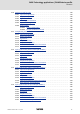
9400 Technology applications | CiA402 device profile Parameter setting & configuration Common entries 0x6502 - Supported drive modes Index | Name: Data type: UNSIGNED_32 Code: C03521 0x6502 | Supported drive modes Bit coded display in which operating modes the drive can be operated. 0: operating mode is not supported. 1: operating mode is supported.
9400 Technology applications | CiA402 device profile Parameter setting & configuration Common entries 0x6503 - Drive catalogue number Index | Name: Data type: VISIBLE_STRING Code: C03522 0x6503 | Drive catalogue number Drive catalogue number ; Read access ; Write access CINH PLC-STOP PDO_MAP_RX PDO_MAP_TX 0x6504 - Drive manufacturer Index | Name: Data type: VISIBLE_STRING Code: C03512 0x6504 | Drive manufacturer Drive manufacturer ; Read access ; Write access CINH PLC-STOP PDO_MAP_RX PDO_MAP_TX
9400 Technology applications | CiA402 device profile Parameter setting & configuration Common entries 0x60FE - Digital outputs Index | Name: Data type: UNSIGNED_8 Code: C03516 0x60FE | Digital outputs Data structure for the digital outputs. Subindex Name 0x60FE/1 Physical outputs 0x60FE/2 Bit mask Index | Name: Data type: UNSIGNED_8 Code: C03517 0x60FE/1 | Physical outputs Status of the digital outputs.
9400 Technology applications | CiA402 device profile Parameter setting & configuration Common entries 3.6.2 Motor data The motor data are set via the Lenze parameters of the motor control. 40 L EDS94TA11010xxxx EN 1.
9400 Technology applications | CiA402 device profile Parameter setting & configuration Device control 3.7 Device control The objects described in this chapter serve to control the states of the controller and select the operating mode. 3.7.1 Object description All objects correspond to the CiA402 specification, but some of them have only a restricted value range.
9400 Technology applications | CiA402 device profile Parameter setting & configuration Device control 0x6040 - Control word Index | Name: Data type: UNSIGNED_16 Code: C03530 0x6040 | Control word Control word for the drive.
9400 Technology applications | CiA402 device profile Parameter setting & configuration Device control 0x6041 - Status word Index | Name: Data type: UNSIGNED_16 Code: C03531 0x6041 | Status word Status word from the drive.
9400 Technology applications | CiA402 device profile Parameter setting & configuration Device control 0x605A - Quick stop option code Index | Name: Data type: INTEGER_16 Code: C03534 0x605A | Quick stop option code Response to request for quick stop. 2 = activate quick stop. quick stop Setting range (min. value | unit | max.
9400 Technology applications | CiA402 device profile Parameter setting & configuration Device control 0x6060 - Mode of operation Index | Name: Data type: INTEGER_8 Code: C03537 0x6060 | Mode of operation Selection of operating mode. • The current operating mode is displayed in 0x6061.
9400 Technology applications | CiA402 device profile Parameter setting & configuration Device control 3.7.
9400 Technology applications | CiA402 device profile Parameter setting & configuration Device control 3.7.2.1 Shutdown Bit pattern for "Shutdown" command in 0x6040 (control word): Bit 7 Reset fault 0 Bit 6 Bit 5 Bit 4 Operating mode-dependent control bits X X X Bit 3 Bit 2 Bit 1 Bit 0 Enable operation Quick stop Enable voltage Switch on X 1 1 0 This command changes the device status from "Switch on disabled" to "Ready to switch on".
9400 Technology applications | CiA402 device profile Parameter setting & configuration Device control 3.7.2.2 Switch on Bit pattern for "Switch on" command in 0x6040 (control word): Bit 7 Reset fault 0 Bit 6 Bit 5 Bit 4 Operating mode-dependent control bits X X X Bit 3 Bit 2 Bit 1 Bit 0 Enable operation Quick stop Enable voltage Switch on X 1 1 1 This command serves to deactivate the switch on inhibit which is active after switch on or after the reset (acknowledgement) of an error.
9400 Technology applications | CiA402 device profile Parameter setting & configuration Device control 3.7.2.3 Enable operation Bit pattern for "Enable operation" command in 0x6040 (control word): Bit 7 Reset fault 0 Bit 6 Bit 5 Bit 4 Operating mode-dependent control bits X X X Bit 3 Bit 2 Bit 1 Bit 0 Enable operation Quick stop Enable voltage Switch on 1 1 1 1 This command serves to enable the operation and stop an active quick stop again.
9400 Technology applications | CiA402 device profile Parameter setting & configuration Device control 3.7.2.4 Quick stop Bit pattern for "quick stop" command in 0x6040 (control word): Bit 7 Reset fault 0 Bit 6 Bit 5 Bit 4 Operating mode-dependent control bits X X X Bit 3 Bit 2 Bit 1 Bit 0 Enable operation Quick stop Enable voltage Switch on X 0 1 X This command serves to activate Quick stop when the operation is enabled.
9400 Technology applications | CiA402 device profile Parameter setting & configuration Device control 3.7.2.5 Disable operation Bit pattern for "Disable operation" command in 0x6040 (control word): Bit 7 Reset fault 0 Bit 6 Bit 5 Bit 4 Operating mode-dependent control bits X X X Bit 3 Bit 2 Bit 1 Bit 0 Enable operation Quick stop Enable voltage Switch on 0 1 1 1 This command serves to inhibit the enabled operation again. The pulse inhibit is set.
9400 Technology applications | CiA402 device profile Parameter setting & configuration Device control 3.7.2.6 Disable voltage Bit pattern for "Disable voltage" command in 0x6040 (control word): Bit 7 Reset fault 0 Bit 6 Bit 5 Bit 4 Operating mode-dependent control bits X X X Bit 3 Bit 2 Bit 1 Bit 0 Enable operation Quick stop Enable voltage Switch on X X 0 X This command serves to inhibit the output stages of the controller again.
9400 Technology applications | CiA402 device profile Parameter setting & configuration Device control 3.7.2.7 Reset fault Bit pattern for "Reset fault" command in 0x6040 (control word): Bit 7 Reset fault 0Ê1 Bit 6 Bit 5 Bit 4 Operating mode-dependent control bits X X X Bit 3 Bit 2 Bit 1 Bit 0 Enable operation Quick stop Enable voltage Switch on X X X X This command serves to acknowledge an existing error message if the cause of the error has been eliminated.
9400 Technology applications | CiA402 device profile Parameter setting & configuration Device control 3.7.
9400 Technology applications | CiA402 device profile Parameter setting & configuration Device control 3.7.3.1 Not ready to switch on Bit pattern for "Not ready to switch on" device state in 0x6041 (status word): Bit 7 Bit 6 Bit 5 Bit 4 Bit 3 Bit 2 Bit 1 Bit 0 Warning Switch on disabled Quick stop Voltage enabled Fault Operation enabled Switched on Ready to switch on X 0 X X 0 0 0 0 This is the controller status directly after switching on the supply voltage.
9400 Technology applications | CiA402 device profile Parameter setting & configuration Device control 3.7.3.2 Switch on disabled Bit pattern for device state "Switch on disabled" in 0x6041 (status word): Bit 7 Bit 6 Bit 5 Bit 4 Bit 3 Bit 2 Bit 1 Bit 0 Warning Switch on disabled Quick stop Voltage enabled Fault Operation enabled Switched on Ready to switch on X 1 X X 0 0 0 0 This is the controller's status after the device has been initialised successfully.
9400 Technology applications | CiA402 device profile Parameter setting & configuration Device control 3.7.3.
9400 Technology applications | CiA402 device profile Parameter setting & configuration Device control 3.7.3.6 Quick stop active Bit pattern for device state "Quick stop active" in 0x6041 (status word): Bit 7 Bit 6 Bit 5 Bit 4 Bit 3 Bit 2 Bit 1 Bit 0 Warning Switch on disabled Quick stop Voltage enabled Fault Operation enabled Switched on Ready to switch on X 0 0 X 0 1 1 1 This device state is active if Quick stop is executed or active.
9400 Technology applications | CiA402 device profile Parameter setting & configuration Device control 3.7.3.8 Fault Bit pattern for the "Fault" device state in 0x6041 (status word): Bit 7 Bit 6 Bit 5 Bit 4 Bit 3 Bit 2 Bit 1 Bit 0 Warning Switch on disabled Quick stop Voltage enabled Fault Operation enabled Switched on Ready to switch on X 0 X X 1 0 0 0 If a grave error occurs, i.e.
9400 Technology applications | CiA402 device profile Parameter setting & configuration Device control 3.7.4 Operating mode changeover The drive behaviour depends on the operating mode selected. The operating mode changeover is executed via the 0x6060 object (mode of operation) in the communication states PREOPERATIONAL or OPERATIONAL by the master control. Access is possible via SDO or PDO. Only one operating mode at a time can be active.
9400 Technology applications | CiA402 device profile Parameter setting & configuration Device control 3.7.5 Stop The standard stop of the drive will be automatically activated by the internal state machine if the operating mode selected in the 0x6060 object (mode of operation) is deactivated again and the drive is not yet at standstill. The drive is braked to standstill via a parameterisable deceleration ramp.
9400 Technology applications | CiA402 device profile Parameter setting & configuration Device control 3.7.6 Quick stop Unlike the Stopfunction, quick stop (QSP) is required for a stop in the event of an error. If quick stop is activated, the drive will be braked to standstill irrespective of the defined setpoint within the deceleration time set.
9400 Technology applications | CiA402 device profile Parameter setting & configuration Device control 3.7.7 Controller inhibit Setting the controller inhibit inhibits the power stages in the controller and resets the speed, current, and position controller of the motor control. The controller can be inhibited by different sources, e.g. – by the master control using the "Shutdown" command. – using the RFR digital input. – using the C00002 = "41: Inhibit controller" device command.
9400 Technology applications | CiA402 device profile Parameter setting & configuration Factor group 3.8 Factor group The objects described in this chapter serve to scale physical values. 3.8.
9400 Technology applications | CiA402 device profile Parameter setting & configuration Factor group 0x607E - Polarity Index | Name: Data type: UNSIGNED_8 Code: C03583 0x607E | Polarity Mounting directions Subindex Name 0x607E/1 Polarity of motor 0x607E/2 Polarity of load Index | Name: Data type: UNSIGNED_32 Code: C02527 0x607E/1 | Polarity of motor Motor mounting direction • Direct mapping of the Lenze code C02527 (motor mounting direction). Setting range (min. value | unit | max.
9400 Technology applications | CiA402 device profile Parameter setting & configuration Factor group 0x608B - Velocity notation index Index | Name: Data type: INTEGER_8 Code: C03552 0x608B | Velocity notation index Multiplier for speed values (10 exp value, decimal point) Setting range (min. value | unit | max.
9400 Technology applications | CiA402 device profile Parameter setting & configuration Factor group 0x608F - Position encoder resolution Index | Name: Data type: UNSIGNED_32 Code: C03556 0x608F | Position encoder resolution Resolution of the position encoder Subindex Name 0x608F/1 Encoder increments 0x608F/2 Motor revolution Index | Name: Data type: UNSIGNED_32 Code: C03557 0x608F/1 | Encoder increments Incremental encoder pulses Setting range (min. value | unit | max.
9400 Technology applications | CiA402 device profile Parameter setting & configuration Factor group 0x6091 - Gear ratio Index | Name: Data type: UNSIGNED_32 Code: C03562 0x6091 | Gear ratio Gearbox factor Subindex Name 0x6091/1 Motor revolutions 0x6091/2 Shaft revolutions Index | Name: Data type: UNSIGNED_32 Code: C02520 0x6091/1 | Motor revolutions Number of drive shaft revolutions • Direct mapping of the Lenze code C02520 (gearbox factor numerator: motor). Setting range (min. value | unit | max.
9400 Technology applications | CiA402 device profile Parameter setting & configuration Factor group 0x6092 - Feed constant Index | Name: Data type: UNSIGNED_32 Code: C03565 0x6092 | Feed constant Feed constant • The feed constant corresponds to the motion of the machine at one revolution of the gearbox output shaft. Subindex Name 0x6092/1 Feed 0x6092/2 Shaft revolutions Index | Name: Data type: UNSIGNED_32 Code: C02524 0x6092/1 | Feed Feed • Direct mapping of the Lenze code C02524 (feed constant).
9400 Technology applications | CiA402 device profile Parameter setting & configuration Factor group 0x6093 - Position factor Index | Name: Data type: UNSIGNED_32 Code: C03568 0x6093 | Position factor Factor for position conversions • Application unit internal unit • Internal unit application unit Subindex Name 0x6093/1 Numerator 0x6093/2 Divisor Index | Name: Data type: UNSIGNED_32 Code: C03569 0x6093/1 | Numerator Setting range (min. value | unit | max.
9400 Technology applications | CiA402 device profile Parameter setting & configuration Factor group 0x6095 - Velocity factor 1 Index | Name: Data type: UNSIGNED_32 Code: C03574 0x6095 | Velocity factor 1 Factor for speed conversions • Application unit internal unit • Internal unit application unit Subindex Name 0x6095/1 Numerator 0x6095/2 Divisor Index | Name: Data type: UNSIGNED_32 Code: C03575 0x6095/1 | Numerator Setting range (min. value | unit | max.
9400 Technology applications | CiA402 device profile Parameter setting & configuration Factor group 0x6097 - Acceleration factor Index | Name: Data type: UNSIGNED_32 Code: C03580 0x6097 | Acceleration factor Factor for acceleration conversions • Application unit internal unit • Internal unit application unit Subindex Name 0x6097/1 Numerator 0x6097/2 Divisor Index | Name: Data type: UNSIGNED_32 Code: C03581 0x6097/1 | Numerator Setting range (min. value | unit | max.
9400 Technology applications | CiA402 device profile Parameter setting & configuration Homing mode 3.9 Homing mode In this operating mode, homing can be executed to transmit the measuring system of the machine to the controller within the physically possible travel range. Danger! Note! During homing operations, specially assigned profile parameters are effective.
9400 Technology applications | CiA402 device profile Parameter setting & configuration Homing mode 3.9.
9400 Technology applications | CiA402 device profile Parameter setting & configuration Homing mode 3.9.2 Object description All objects are Lenze-specific. The 0x609A object (homing acceleration) is executed as an array according to the 0x6099 object (homing speeds). All CiA402 homing modes are supported. The homing modes of the "Homing" basic function are supported 1:1.
9400 Technology applications | CiA402 device profile Parameter setting & configuration Homing mode 0x607C - Home position Index | Name: Data type: INTEGER_32 Code: C02642 0x607C | Home position Position which is set as current position during a reference search in the home position or when setting the reference. • Direct illustration of the Lenze code C02642 (reference position). Setting range (min. value | unit | max.
9400 Technology applications | CiA402 device profile Parameter setting & configuration Homing mode 0x6099 - Homing speeds Index | Name: Data type: UNSIGNED_32 Code: C03612 0x6099 | Homing speeds For the reference search two speeds can be parameterised to reduce homing time and increase accuracy: Subindex Name 0x6099/1 Speed during search for switch 0x6099/2 Speed during search for zero Index | Name: Data type: UNSIGNED_32 Code: C02644 0x6099/1 | Speed during search for switch Speed 1 which causes
9400 Technology applications | CiA402 device profile Parameter setting & configuration Homing mode 0x609A - Homing acceleration Index | Name: Data type: UNSIGNED_32 Code: C03615 0x609A | Homing acceleration For the reference search two accelerations (and decelerations) can be parameterised to reduce homing time and increase accuracy: Subindex Name 0x609A/1 Acc. during search for switch 0x609A/2 Acc. during search for zero Index | Name: Data type: UNSIGNED_32 Code: C02645 0x609A/1 | Acc.
9400 Technology applications | CiA402 device profile Parameter setting & configuration Homing mode 3.9.4 Homing mode The reference (e.g. zero position of the drive axis in the machine measuring system) can be defined by reference search or reference setting. In the event of a reference search, the drive travels according to the defined homing mode to detect the reference in the measuring system independently.
9400 Technology applications | CiA402 device profile Parameter setting & configuration Homing mode 3.9.5 Home position & target position If the reference position is set during reference search, this selected position in the machine measuring system corresponds to the value set in the object 0x607C (home offset). Afterwards, the drive proceeds according to the mode parameterised in the object 0x60FB/ 7 (homing stop mode). See the following chapter "Drive behaviour after setting the home position". 3.9.
9400 Technology applications | CiA402 device profile Parameter setting & configuration Homing mode 3.9.7 Profile data set change-over For the reference search two profile data sets with different speeds and accelerations can be parameterised to reduce the homing time and increase the accuracy: With the profile data set 1 first the limit switch/reference switch (depending on the mode selected) is quickly approached.
9400 Technology applications | CiA402 device profile Parameter setting & configuration Homing mode 3.9.8 Overview of CiA402 homing modes Short overview CiA402 homing method Evaluated signals/sensors Encoder zero pulse/ touch probe sensor Negative travel range limit switch -2 Positive direction of rotation at torque limit. -1 Negative direction of rotation at torque limit.
9400 Technology applications | CiA402 device profile Parameter setting & configuration Homing mode Note! Profile data set change-over For the reference search two profile data sets with different speeds and accelerations can be parameterised to reduce the homing time and increase the accuracy. Profile data set change-over ( 81) The following process descriptions give information about when exactly the change-over to profile data set 2 takes place in the corresponding homing mode.
9400 Technology applications | CiA402 device profile Parameter setting & configuration Homing mode CiA402 Homing method -2 1 Process: 1. Movement in positive direction with reduced torque and profile data set 1. 2. "Homing to end stop": When the drive hits an end stop so that the torque limit set in C02649 is exceeded for the blocking time defined in C02650 the (0x607C) reference is set. 3. Absolute positioning to target position (C02643) with profile data set 2 (if 0x60FB/ 7 = "0").
9400 Technology applications | CiA402 device profile Parameter setting & configuration Homing mode CiA402 Homing method 01 1 0 1 Touch probe/zero pulse Negative travel range limit switch Process: 1. Movement in negative direction with profile data set 1. 2. Reversing to negative travel range limit switch and change to profile data set 2. 3. Negative edge of the travel range limit switch activates touch probe detection. 4.
9400 Technology applications | CiA402 device profile Parameter setting & configuration Homing mode CiA402 Homing method 02 1 0 1 Touch probe/zero pulse Positive travel range limit switch Process: 1. Movement in positive direction with profile data set 1. 2. Reversing to positive travel range limit switch and change to profile data set 2. 3. Negative edge of the travel range limit switch activates touch probe detection. 4.
9400 Technology applications | CiA402 device profile Parameter setting & configuration Homing mode CiA402 Homing method 03 1 2 0 1 Touch probe/zero pulse Reference switch Processes: Case 1: Axis has not yet activated reference switch: 1. Movement in positive direction with profile data set 1. 2. Reversing with positive edge of the reference switch and change to profile data set 2. 3. Negative edge of the reference switch activates touch probe detection. 4.
9400 Technology applications | CiA402 device profile Parameter setting & configuration Homing mode CiA402 Homing method 04 1 2 0 1 Touch probe/zero pulse Reference switch Processes: Case 1: Axis has not yet activated reference switch: 1. Movement in positive direction with profile data set 1. 2. Positive edge of the reference switch activates touch probe detection and change to profile data set 2. 3.
9400 Technology applications | CiA402 device profile Parameter setting & configuration Homing mode CiA402 Homing method 05 1 2 0 1 Touch probe/zero pulse Reference switch Processes: Case 1: Axis has not yet activated reference switch: 1. Movement in negative direction with profile data set 1. 2. Reversing with positive edge of the reference switch and change to profile data set 2. 3. Negative edge of the reference switch activates touch probe detection. 4.
9400 Technology applications | CiA402 device profile Parameter setting & configuration Homing mode CiA402 Homing method 06 1 2 0 1 Touch probe/zero pulse Reference switch Processes: Case 1: Axis has not yet activated reference switch: 1. Movement in negative direction with profile data set 1. 2. Positive edge of the reference switch activates touch probe detection and change to profile data set 2. 3.
9400 Technology applications | CiA402 device profile Parameter setting & configuration Homing mode CiA402 Homing method 07 1 2 3 0 1 2 Touch probe/zero pulse Reference switch Positive travel range limit switch Processes: Case 1: Axis does not activate reference switch on the way to the limit switch: 1. Movement in positive direction with profile data set 1. 2. Reversing to positive travel range limit switch. 3. Positive edge of the reference switch activates profile data set 2. 4.
9400 Technology applications | CiA402 device profile Parameter setting & configuration Homing mode Case 3: Axis already stands on reference switch: 1. Movement in negative direction with profile data set 2. 2. Negative edge of the reference switch activates touch probe detection. 3. The following positive edge of the encoder zero pulse/touch probe sensor sets the reference (0x607C). 4. Absolute positioning to target position (C02643) with profile data set 2 (if 0x60FB/ 7 = "0").
9400 Technology applications | CiA402 device profile Parameter setting & configuration Homing mode Case 2: Axis activates reference switch first on the way to the limit switch: 1. Movement in positive direction with profile data set 1. 2. Positive edge of the reference switch activates touch probe detection and change to profile data set 2. 3. The following positive edge of the encoder zero pulse/touch probe sensor sets the reference (0x607C). 4.
00 Technology applications | CiA402 device profile Parameter setting & configuration Homing mode Processes: Case 1: Axis does not activate reference switch on the way to the limit switch: 1. Movement in positive direction with profile data set 1. 2. Reversing to positive travel range limit switch. 3. Positive edge of the reference switch activates touch probe detection and change to profile data set 2. 4.
9400 Technology applications | CiA402 device profile Parameter setting & configuration Homing mode CiA402 Homing method 10 1 2 3 0 1 2 Touch probe/zero pulse Reference switch Positive travel range limit switch Processes: Case 1: Axis does not activate reference switch on the way to the limit switch: 1. Movement in positive direction with profile data set 1. 2. Reversing to positive travel range limit switch. 3.
9400 Technology applications | CiA402 device profile Parameter setting & configuration Homing mode Case 3: Axis already stands on reference switch: 1. Movement in positive direction with profile data set 2. 2. Negative edge of the reference switch activates touch probe detection. 3. The following positive edge of the encoder zero pulse/touch probe sensor sets the reference (0x607C). 4. Absolute positioning to target position (C02643) with profile data set 2 (if 0x60FB/ 7 = "0").
9400 Technology applications | CiA402 device profile Parameter setting & configuration Homing mode Case 2: Axis activates reference switch first on the way to the limit switch: 1. Movement in negative direction with profile data set 1. 2. Reversing with positive edge of the reference switch and change to profile data set 2. 3. Negative edge of the reference switch activates touch probe detection. 4. The following positive edge of the encoder zero pulse/touch probe sensor sets the reference (0x607C). 5.
9400 Technology applications | CiA402 device profile Parameter setting & configuration Homing mode Processes: Case 1: Axis does not activate reference switch on the way to the limit switch: 1. Movement in negative direction with profile data set 1. 2. Reversing to negative travel range limit switch. 3. Positive edge of the reference switch activates profile data set 2. 4. Reversing with negative edge of reference switch. 5. Positive edge of the reference switch activates touch probe detection. 6.
9400 Technology applications | CiA402 device profile Parameter setting & configuration Homing mode CiA402 Homing method 13 1 2 3 0 1 2 Touch probe/zero pulse Reference switch Negative travel range limit switch Processes: Case 1: Axis does not activate reference switch on the way to the limit switch: 1. Movement in negative direction with profile data set 1. 2. Reversing to negative travel range limit switch. 3.
9400 Technology applications | CiA402 device profile Parameter setting & configuration Homing mode Case 3: Axis already stands on reference switch: 1. Movement in negative direction with profile data set 2. 2. Reversing with negative edge of reference switch. 3. Positive edge of the reference switch activates touch probe detection. 4. The following positive edge of the encoder zero pulse/touch probe sensor sets the reference (0x607C). 5.
9400 Technology applications | CiA402 device profile Parameter setting & configuration Homing mode Case 2: Axis activates reference switch first on the way to the limit switch: 1. Movement in negative direction with profile data set 1. 2. Positive edge of the reference switch activates profile data set 2. 3. Negative edge of the reference switch activates touch probe detection. 4. The following positive edge of the encoder zero pulse/touch probe sensor sets the reference (0x607C). 5.
9400 Technology applications | CiA402 device profile Parameter setting & configuration Homing mode CiA402 Homing method 17 1 0 Negative travel range limit switch Process: 1. Movement in negative direction with profile data set 1. 2. Reversing to negative travel range limit switch and change to profile data set 2. 3. The following negative edge of travel range limit switch sets reference (0x607C). 4. Absolute positioning to target position (C02643) with profile data set 2 (if 0x60FB/ 7 = "0").
9400 Technology applications | CiA402 device profile Parameter setting & configuration Homing mode CiA402 Homing method 19 1 2 0 Homing switch Processes: Case 1: Axis has not yet activated reference switch: 1. Movement in positive direction with profile data set 1. 2. Reversing with positive edge of the reference switch and change to profile data set 2. 3. The following negative edge of reference switch sets reference (0x607C). 4.
9400 Technology applications | CiA402 device profile Parameter setting & configuration Homing mode CiA402 Homing method 20 1 2 0 Homing switch Processes: Case 1: Axis has not yet activated reference switch: 1. Movement in positive direction with profile data set 1. 2. The following positive edge of reference switch sets reference (0x607C). 3. Absolute positioning to target position (C02643) with profile data set 2 (if 0x60FB/ 7 = "0"). Case 2: Axis already stands on reference switch: 1.
9400 Technology applications | CiA402 device profile Parameter setting & configuration Homing mode CiA402 Homing method 21 1 2 0 Homing switch Processes: Case 1: Axis has not yet activated reference switch: 1. Movement in negative direction with profile data set 1. 2. Reversing with positive edge of the reference switch and change to profile data set 2. 3. The following negative edge of reference switch sets reference (0x607C). 4.
9400 Technology applications | CiA402 device profile Parameter setting & configuration Homing mode CiA402 Homing method 22 1 2 0 Homing switch Processes: Case 1: Axis has not yet activated reference switch: 1. Movement in negative direction with profile data set 1. 2. The following positive edge of reference switch sets reference (0x607C). 3. Absolute positioning to target position (C02643) with profile data set 2 (if 0x60FB/ 7 = "0"). Case 2: Axis already stands on reference switch: 1.
9400 Technology applications | CiA402 device profile Parameter setting & configuration Homing mode CiA402 Homing method 23 1 2 3 0 1 Homing switch Positive travel range limit switch Processes: Case 1: Axis does not activate reference switch on the way to the limit switch: 1. Movement in positive direction with profile data set 1. 2. Reversing to positive travel range limit switch. 3. Positive edge of the reference switch activates profile data set 2. 4.
9400 Technology applications | CiA402 device profile Parameter setting & configuration Homing mode CiA402 Homing method 24 1 2 3 0 1 Homing switch Positive travel range limit switch Processes: Case 1: Axis does not activate reference switch on the way to the limit switch: 1. Movement in positive direction with profile data set 1. 2. Reversing to positive travel range limit switch. 3. Positive edge of the reference switch activates profile data set 2. 4.
9400 Technology applications | CiA402 device profile Parameter setting & configuration Homing mode CiA02 homing method 25 1 2 3 0 1 Homing switch Positive travel range limit switch Processes: Case 1: Axis does not activate reference switch on the way to the limit switch: 1. Movement in positive direction with profile data set 1. 2. Reversing to positive travel range limit switch. 3. The following positive edge of reference switch sets reference (0x607C). 4.
9400 Technology applications | CiA402 device profile Parameter setting & configuration Homing mode CiA402 Homing method 26 1 2 3 0 1 Homing switch Positive travel range limit switch Processes: Case 1: Axis does not activate reference switch on the way to the limit switch: 1. Movement in positive direction with profile data set 1. 2. Reversing to positive travel range limit switch. 3. Reversing with positive edge of the reference switch and change to profile data set 2. 4.
9400 Technology applications | CiA402 device profile Parameter setting & configuration Homing mode CiA402 Homing method 27 1 2 3 0 1 Homing switch Negative travel range limit switch Processes: Case 1: Axis does not activate reference switch on the way to the limit switch: 1. Movement in negative direction with profile data set 1. 2. Reversing to negative travel range limit switch. 3. Positive edge of the reference switch activates profile data set 2. 4.
9400 Technology applications | CiA402 device profile Parameter setting & configuration Homing mode CiA402 Homing method 28 1 2 3 0 1 Homing switch Negative travel range limit switch Processes: Case 1: Axis does not activate reference switch on the way to the limit switch: 1. Movement in negative direction with profile data set 1. 2. Reversing to negative travel range limit switch. 3. Positive edge of the reference switch activates profile data set 2. 4.
9400 Technology applications | CiA402 device profile Parameter setting & configuration Homing mode CiA402 Homing method 29 1 2 3 0 1 Homing switch Negative travel range limit switch Processes: Case 1: Axis does not activate reference switch on the way to the limit switch: 1. Movement in negative direction with profile data set 1. 2. Reversing to negative travel range limit switch. 3. The following positive edge of reference switch sets reference (0x607C). 4.
9400 Technology applications | CiA402 device profile Parameter setting & configuration Homing mode CiA402 Homing method 30 1 2 3 0 1 Homing switch Negative travel range limit switch Processes: Case 1: Axis does not activate reference switch on the way to the limit switch: 1. Movement in negative direction with profile data set 1. 2. Reversing to negative travel range limit switch. 3. Reversing with positive edge of the reference switch and change to profile data set 2. 4.
9400 Technology applications | CiA402 device profile Parameter setting & configuration Homing mode CiA402 Homing method 31 Reserved: Homing is not carried out. CiA402 Homing method 32 Reserved: Homing is not carried out. CiA402 Homing method 33 1 0 Touch probe/zero pulse Process: 1. Movement in negative direction with profile data set 1 and activation of the touch probe detection. 2. The following positive edge of the touch probe sensor sets the reference (0x607C). 3.
9400 Technology applications | CiA402 device profile Parameter setting & configuration Homing mode CiA402 Homing method 34 1 0 Touch probe/zero pulse Process: 1. Movement in positive direction with profile data set 1 and activation of the touch probe detection. 2. The following positive edge of the touch probe sensor sets the reference (0x607C). 3. Absolute positioning to target position (C02643) with profile data set 2 (if 0x60FB/ 7 = "0"). CiA402 homing method 35 1 Direct reference setting.
9400 Technology applications | CiA402 device profile Parameter setting & configuration Homing mode 3.9.
9400 Technology applications | CiA402 device profile Parameter setting & configuration Homing mode 3.9.10 Basic function "Homing" In "Homing mode" the "Homing" basic function is used. Lenze parameters (short overview) Parameter Lenze setting Value Unit C02528 118 Traversing range Modulo C02640 Homing mode C02641 Action after detect Home position Set home pos. directly C02642 Home position Move absolute on Target position 0.
9400 Technology applications | CiA402 device profile Parameter setting & configuration Position control function 3.10 Position control function The objects described in this chapter serve to control the position control (including following error and in-position recognition), control an optional holding brake and request the status of the safety functions and safe inputs/outputs of the optional SM3xx safety module. 3.10.
9400 Technology applications | CiA402 device profile Parameter setting & configuration Position control function 3.10.2 Object description Except for the 0x60FA object (control effort), all objects correspond to the CiA402 specification.
9400 Technology applications | CiA402 device profile Parameter setting & configuration Position control function 0x6064 - Position actual value unit Index | Name: Data type: INTEGER_32 Code: C03592 0x6064 | Position actual value unit Current position in the user-defined [unit] Display area (min. value | unit | max.
9400 Technology applications | CiA402 device profile Parameter setting & configuration Position control function 0x60F4 - Following error actual value Index | Name: Data type: INTEGER_32 Code: C03597 0x60F4 | Following error actual value Current following error Following error detection Display area (min. value | unit | max.
9400 Technology applications | CiA402 device profile Parameter setting & configuration Position control function Index | Name: Data type: UNSIGNED_8 Code: C03602 0x60FB/2 | Brake control Brake control Value is bit-coded: Information Bit 0 Release brake Release brake Bit 1 Starting torque2 Use starting torque 2 (C02587) Bit 2 Disable stop Do not close brake at standstill Bit 3 Brake applied Status detection via switching contact at the brake Bit 4 Brake test Carry out brake test Bit 5 Brake g
9400 Technology applications | CiA402 device profile Parameter setting & configuration Position control function Index | Name: Data type: UNSIGNED_8 Code: C03605 0x60FB/5 | Safe IO state Status of the safe inputs and outputs of the SM3xx safety module • Which bits are supported depends on the safety module used.
9400 Technology applications | CiA402 device profile Parameter setting & configuration Position control function Index | Name: Data type: UNSIGNED_32 Code: C02641 0x60FB/7 | Homing stop mode Drive behaviour after setting the home position • Direct mapping of the Lenze code C02641 (behaviour after detection of home position) Drive behaviour after setting the home position Selection list (Lenze setting printed in bold) Information 0 Move absolute on Target position After setting the home position (C0
9400 Technology applications | CiA402 device profile Parameter setting & configuration Position control function 3.10.
9400 Technology applications | CiA402 device profile Parameter setting & configuration Position control function 3.10.6 Brake control The function of a holding brake, if available, can be controlled via the 0x60FB/2 object (brake control). Danger! Stop! Please note that the motor holding brake is an important element of the safety concept of the entire machine.
9400 Technology applications | CiA402 device profile Parameter setting & configuration Position control function 3.10.6.1 Signal configuration An external brake is supported by a fixed connection of the BRK_bReleaseBrakeOut output signal of the "Brake control" basic function to the DO1 digital output and the BRK_bBrakeApplied input signal to the DI1 digital input.
9400 Technology applications | CiA402 device profile Parameter setting & configuration Position control function Status monitoring by "Motor holding brake control module status" (See signal path in fig. [3-11]) Indirect status detection of the brake function. Monitoring of the motor holding brake control module and the electrical brake circuit. Status monitoring by "Brake function test" (See signal path in fig.
9400 Technology applications | CiA402 device profile Parameter setting & configuration Position control function 3.10.6.2 Torque feedforward control In automatic operation (mode 2/12) the brake control offers the possibility of precontrolling the required torque of the drive when the brake is released. Note! The torque is precontrolled for one second.
9400 Technology applications | CiA402 device profile Parameter setting & configuration Interpolated position mode 3.11 Interpolated position mode The "Interpolated position mode" is required for a coordinated traversing of axes depending on each other or for traversing of single axes with time interpolation of the setpoints.
9400 Technology applications | CiA402 device profile Parameter setting & configuration Interpolated position mode 3.11.2 Object description All objects correspond to the CiA402 specification, but some of them have only a restricted value range.
9400 Technology applications | CiA402 device profile Parameter setting & configuration Interpolated position mode 0x60C0 - Interpolation sub mode select Index | Name: Data type: INTEGER_16 Code: C03630 0x60C0 | Interpolation sub mode select Interpolation algorithm • If "Linear interpolation" or "Quadratic interpolation" has been selected and no feedforward control values for speed and torque/acceleration are transmitted, it is wise to generate the feedforward values by differentiation of the position si
9400 Technology applications | CiA402 device profile Parameter setting & configuration Interpolated position mode Index | Name: Data type: UNSIGNED_8 Code: C03637 0x60C2/1 | ip time units Basic multiplier for interpolation cycle time Setting range (min. value | unit | max.
9400 Technology applications | CiA402 device profile Parameter setting & configuration Interpolated position mode 0x60C4 - Interpolation data configuration Index | Name: Data type: UNSIGNED_32 Code: C03642 0x60C4 | Interpolation data configuration Configuration of the interpolation data Subindex Name 0x60C4/1 Max.
9400 Technology applications | CiA402 device profile Parameter setting & configuration Interpolated position mode Index | Name: Data type: UNSIGNED_8 Code: C03647 0x60C4/5 | Size of data record Length of the interpolation data in byte Setting range (min. value | unit | max. value) 4 ; Read access ; Write access Lenze setting 4 4 CINH PLC-STOP PDO_MAP_RX PDO_MAP_TX Index | Name: Data type: UNSIGNED_8 Code: C03648 0x60C4/6 | Buffer clear Clear interpolation buffer 1 = Enable interpolation buffer.
EDS94TA11010xxxx EN 1.2 - 03/2010 3.11.
9400 Technology applications | CiA402 device profile Parameter setting & configuration Interpolated position mode Internal variables of the motor control (oscilloscope signals) The red numbers in brackets specified in the signal flow represent internal variables of the motor control which can be recorded with the oscilloscope for diagnostic and documentation purposes. No. 138 Variable of the motor control Meaning (1) Torque.dnTotalTorqueAdd Additive torque feedforward control value (2) Torque.
9400 Technology applications | CiA402 device profile Parameter setting & configuration Interpolated position mode 3.11.4 Setpoint selection The position setpoint for the position follower is selected via the subindex 1 (X1) of the 0x60C1 object (Interpolation data record).
9400 Technology applications | CiA402 device profile Parameter setting & configuration Interpolated position mode 3.11.
9400 Technology applications | CiA402 device profile Parameter setting & configuration Interpolated position mode 3.11.7 Basic function "Position follower" The "Position follower" basic function based on the "Interpolated position mode" serves as setpoint interface for position-controlled drives. The specified position setpoint can either refer to the encoder on the motor side or to the (position) encoder used additionally to detect the machine position.
9400 Technology applications | CiA402 device profile Parameter setting & configuration Cyclic synchronous position mode (IEC 61800-7) 3.12 Cyclic synchronous position mode (IEC 61800-7) This operating mode provides a quick position follower with speed/torque/feed force feedforward control. The motion profile to be processed is defined by the master control.
9400 Technology applications | CiA402 device profile Parameter setting & configuration Cyclic synchronous position mode (IEC 61800-7) Output data Index Name Data type Object type 0x6041 Status word UNSIGNED_16 VAR 0x60FC Position demand value* INTEGER_32 VAR 0x6063 Position actual value* INTEGER_32 VAR 0x60F4 Following error actual value INTEGER_32 VAR Grayed out = read access only 3.12.
9400 Technology applications | CiA402 device profile Parameter setting & configuration Cyclic synchronous position mode (IEC 61800-7) Objects described in this chapter: Index Name Data type Object type 0x607A Target position INTEGER_32 VAR 0x60B0 Offset position INTEGER_32 VAR Grayed out = read access only 0x607A - Target position Index | Name: Data type: INTEGER_32 Code: C03690 0x607A | Target position Position setpoint Setting range (min. value | unit | max.
EDS94TA11010xxxx EN 1.2 - 03/2010 3.12.
9400 Technology applications | CiA402 device profile Parameter setting & configuration Cyclic synchronous position mode (IEC 61800-7) Internal variables of the motor control (oscilloscope signals) The red numbers in brackets specified in the signal flow represent internal variables of the motor control which can be recorded with the oscilloscope for diagnostic and documentation purposes. No. 3.12.4 Variable of the motor control Meaning (1) Torque.
9400 Technology applications | CiA402 device profile Parameter setting & configuration Cyclic synchronous position mode (IEC 61800-7) 3.12.
9400 Technology applications | CiA402 device profile Parameter setting & configuration Cyclic synchronous position mode (IEC 61800-7) 3.12.7 Basic function "Position follower" The "Position follower" basic function based on the "Cyclic synchronous velocity mode" serves as setpoint interface for position-controlled drives. The specified position setpoint can either refer to the encoder on the motor side or to the (position) encoder used additionally to detect the machine position.
9400 Technology applications | CiA402 device profile Parameter setting & configuration Cyclic synchronous velocity mode (IEC 61800-7) 3.13 Cyclic synchronous velocity mode (IEC 61800-7) This operating mode provides a fast speed follower with torque/feed force feedforward control. The speed profile to be processed is defined by the master control.
9400 Technology applications | CiA402 device profile Parameter setting & configuration Cyclic synchronous velocity mode (IEC 61800-7) 3.13.
9400 Technology applications | CiA402 device profile Parameter setting & configuration Cyclic synchronous velocity mode (IEC 61800-7) 0x606C - Velocity actual value Index | Name: Data type: INTEGER_32 Code: C03653 0x606C | Velocity actual value Current speed Display area (min. value | unit | max.
Speed follower SF_bEnable C02527 MI_dnTorqueHighLimit_n C02568/4 0 C02559/1 0 1 Torque offset 0x60B2 Interpolation MI_dnInertiaAdapt_n C02568/8 0 SF_dnTorqueAdd_n Target torque 0x6071 C00276 1 C00273 SF_dnAccAdd_x i C02531/3 0 C00692 1 1 (1) Interpolator 2 C00273 C02550/3 0 3 L C00273 C02550/2 0 SF_dnSpeedSet_n Offset velocity 0x60B1 Target velocity 0x60FF (3) 1 Interpolator Interpolation Unit _s Interpolation time period 0x60C2 SF_dnSpeedAdd_s i C02531/3 MI_dnTorqueLowLimit
9400 Technology applications | CiA402 device profile Parameter setting & configuration Cyclic synchronous velocity mode (IEC 61800-7) Internal variables of the motor control (oscilloscope signals) The red numbers in brackets specified in the signal flow represent internal variables of the motor control which can be recorded with the oscilloscope for diagnostic and documentation purposes. No. 3.13.4 Variable of the motor control Meaning (1) Torque.
9400 Technology applications | CiA402 device profile Parameter setting & configuration Cyclic synchronous velocity mode (IEC 61800-7) 3.13.
9400 Technology applications | CiA402 device profile Parameter setting & configuration Cyclic synchronous velocity mode (IEC 61800-7) 3.13.7 Basic function "Speed follower" The "Speed follower" basic function based on the "Cyclic synchronous velocity mode" serves as setpoint interface for speed-controlled drives. The motor control is switched over automatically to speed control with torque limitation.
9400 Technology applications | CiA402 device profile Parameter setting & configuration Cyclic synchronous torque mode (IEC 61800-7) 3.14 Cyclic synchronous torque mode (IEC 61800-7) This operating mode provides a fast torque follower with speed limitation. The torque profile to be processed is defined by the master control.
9400 Technology applications | CiA402 device profile Parameter setting & configuration Cyclic synchronous torque mode (IEC 61800-7) 3.14.
9400 Technology applications | CiA402 device profile Parameter setting & configuration Cyclic synchronous torque mode (IEC 61800-7) 0x6071 - Target torque Index | Name: Data type: INTEGER_32 Code: C03670 0x6071 | Target torque Setpoint for torque or torque feedforward control • The object is internally limited to ±1073741824 (≡ ±100%). • 230 ≡ 100 % motor reference torque (C00057/2) Setting range (min. value | unit | max.
9400 Technology applications | CiA402 device profile Parameter setting & configuration Cyclic synchronous torque mode (IEC 61800-7) 0x6076 - Motor rated torque Index | Name: Data type: UNSIGNED_32 Code: C00057/2 0x6076 | Motor rated torque Rated motor torque Display area (min. value | unit | max.
9400 Technology applications | CiA402 device profile Parameter setting & configuration Cyclic synchronous torque mode (IEC 61800-7) 0x6088 - Torque profile type Index | Name: Data type: INTEGER_16 Code: C03680 0x6088 | Torque profile type Torque profile 0 = Linear ramp (interpolation). Setting range (min. value | unit | max.
9400 Technology applications | CiA402 device profile Parameter setting & configuration Cyclic synchronous torque mode (IEC 61800-7) 0x60F7 - Power stage parameters Index | Name: Data type: UNSIGNED_32 Code: C03681 0x60F7 | Power stage parameters Power stage parameters Display area (min. value | unit | max. value) 0 ; Read access 0 Write access EDS94TA11010xxxx EN 1.
Torque follower TF_bEnable C02527 0 MI_dnTorqueHighLimit_n C02568/4 C02559/1 0 1 C02550/2 Positive speed limit 0x60F6/1 Torque offset 0x60B2 TF_dnSpeedHighLimit_n 0 Interpolator (1) 1 50 min-1 0 TF_dnTorqueSet_n MI_bSpeedSetpointLimited C02569/5 C02550/3 Interpolator C00695 1 Interpolation time period 0x60C2 L Negative speed limit 0x60F6/2 TF_dnSpeedLowLimit_n 0 0 C02550/2 Interpolator MI_dnTorqueLowLimit_n C02568/5 0 (2) 0 1 Motordrehzahl Geberauswertung C00772 p Signal of th
9400 Technology applications | CiA402 device profile Parameter setting & configuration Cyclic synchronous torque mode (IEC 61800-7) Internal variables of the motor control (oscilloscope signals) The red numbers in brackets specified in the signal flow represent internal variables of the motor control which can be recorded with the oscilloscope for diagnostic and documentation purposes. 3.14.4 No. Variable of the motor control Meaning (1) Speed.dnSpeedSetpoint Speed setpoint (2) Speed.
9400 Technology applications | CiA402 device profile Parameter setting & configuration Cyclic synchronous torque mode (IEC 61800-7) 3.14.
9400 Technology applications | CiA402 device profile Parameter setting & configuration Cyclic synchronous torque mode (IEC 61800-7) 3.14.7 Basic function "Torque follower" The "Torque follower" basic function based on the "Cyclic synchronous torque mode" serves as setpoint interface for torque-controlled drives. The motor control is switched over automatically to torque control with speed limitation.
9400 Technology applications | CiA402 device profile Parameter setting & configuration Touch probe 3.15 Touch probe Up to 2 touch probe channels can be used in parallel. Possible touch probe sources: – TP1 : Zero pulse position encoder or digital input DI7 – TP2 : Zero pulse position encoder or digital input DI8 Configuration: see control word 0x60B8 (Touch probe function) 3.15.
9400 Technology applications | CiA402 device profile Parameter setting & configuration Touch probe 0x60B8 - Touch probe function Index | Name: Data type: UNSIGNED_16 Code: C03700 0x60B8 | Touch probe function Control word for the configuration of the touch probe functionality Value is bit-coded: Information Bit 0 0: Deactivate touch probe 1 1: Activate touch probe 1 Configuration of the touch probe channel 1 Bit 1 0: Record first event only 1: Record all events Bit 2 Source for touch probe 1 0: Digit
9400 Technology applications | CiA402 device profile Parameter setting & configuration Touch probe 0x60B9 - Touch probe status Index | Name: Data type: UNSIGNED_16 Code: C03701 0x60B9 | Touch probe status Status of the touch probe functionality Value is bit-coded: Information Bit 0 0: Touch probe 1 deactivated 1: Touch probe 1 activated Status of the touch probe channel 1 Bit 1 Evaluation of positive edge 0: Deactivated 1: Activated Bit 2 Evaluation of negative edge 0: Deactivated 1: Activated Bit 3 .
9400 Technology applications | CiA402 device profile Parameter setting & configuration Touch probe 0x60BB - Touch probe pos 1 neg value Index | Name: Data type: INTEGER_32 Code: C03707 0x60BB | Touch probe pos 1 neg value Touch probe position 1, detected with negative edge. Display area (min. value | unit | max.
9400 Technology applications | CiA402 device profile Parameter setting & configuration Touch probe 3.15.3 Internal interfaces | function block "L_CiA402TouchProbe" The IM L_CiA402TouchProbe provides the interfaces for the touch probe functionality of the device profile CiA402 in the function block editor.
9400 Technology applications | CiA402 device profile Parameter setting & configuration Touch probe Outputs Identifier Info/meaning Data type wCiA402TouchProbeState WORD dnCiA402 TouchProbe1PosVal_e4 DINT dnCiA402 TouchProbe1PosVal_p DINT dnCiA402 TouchProbe1NegVal_e4 DINT dnCiA402 TouchProbe1NegVal_p DINT dnCiA402 TouchProbe2PosVal_e4 DINT dnCiA402 TouchProbe2PosVal_p DINT dnCiA402 TouchProbe2NegVal_e4 DINT dnCiA402 TouchProbe2NegVal_p DINT bTP1_bEnablePosEdge Interface to the master / master c
9400 Technology applications | CiA402 device profile Parameter setting & configuration Torque limiting 3.16 Torque limiting Selecting the torque limits of the drive. 3.16.1 Input and output data Input data 3.16.
9400 Technology applications | CiA402 device profile Parameter setting & configuration Parameterisable additional functions 3.17 Parameterisable additional functions 3.17.1 Undervoltage recognition of the DC link C03001 serves to parameterise an undervoltage recognition of the DC link. For this, the DC link voltage measured by the motor interface is compared to the voltage limit set in C03001.
9400 Technology applications | CiA402 device profile Parameter setting & configuration Parameterisable additional functions 3.17.3 Dynamic change of the proportional gain Vp of the speed controller The dynamic change of the speed controller gain during operation can be parameterised as a function of the desired speed by a characteristic. The characteristic is defined by the parameters C04100 ... C04102 of the function block Adaption_Speedcontroller which is an instance of the function block L_TbCurve.
9400 Technology applications | CiA402 device profile Parameter setting & configuration Using the FB Editor 3.18 Using the FB Editor From »Engineer« version 2.12, the CiA402 application (as of V2.x) can be edited with the FB Editor, which means that e.g. other function blocks can be added to the interconnection. Note! • Please observe that deleting existing interconnections will affect basic functions of the CiA402 application! • New port variables cannot be created.
9400 Technology applications | CiA402 device profile Parameter setting & configuration Internal interfaces | function block "L_CiA402DeviceProfile" 3.19 Internal interfaces | function block "L_CiA402DeviceProfile" The L_CiA402DeviceProfile function block contains the main functionality of the CiA402 device profile.
9400 Technology applications | CiA402 device profile Parameter setting & configuration Internal interfaces | function block "L_CiA402DeviceProfile" Identifier Information/possible settings Data type bQSP_bActive BOOL bDI_bReady BOOL bDI_bFailActive BOOL bDI_bImpActive BOOL bDI_bCInhActive BOOL bDI_bWarningActive BOOL bDI_bMainSupplyOk WORD bBRK_bCInhActive BOOL bBRK_dnState BOOL From technology application V2.
9400 Technology applications | CiA402 device profile Parameter setting & configuration Internal interfaces | function block "L_CiA402DeviceProfile" Identifier Information/possible settings Data type bMI_ bMotorOrientationInverse BOOL bMI_ bSpeedBelowThresholdC19 BOOL bPF_bEnabled BOOL bSF_bEnabled BOOL bTF_bEnabled BOOL dnSMI_dnState DINT bSYNC_ bProcessDataExpected Interface for the motor interface • Input for the motor mounting position.
9400 Technology applications | CiA402 device profile Parameter setting & configuration Internal interfaces | function block "L_CiA402DeviceProfile" Identifier Info/meaning Data type dnCiA402ActualSpeed_e4 DINT dnCiA402ActualTorque_n DINT dnCiA402ActualCurrent_n Interface to the master / master control • Actual torque in [%] DINT Interface to the master / master control • Actual motor current in [%] BYTE Interface to the master / master control • States of the digital inputs.
9400 Technology applications | CiA402 device profile Parameter setting & configuration Internal interfaces | function block "L_CiA402DeviceProfile" Identifier Info/meaning Data type dnSetPos_p Interface for the selection of the position setpoint DINT dnSetOrAddSpeed_s DINT Interface for the selection of the speed setpoint or the speed feedforward control value DINT Interface for the selection of the speed setpoint or the speed feedforward control value dnSetOrAddTorque_n Interface for the selectio
9400 Technology applications | CiA402 device profile Parameter setting & configuration Application error messages 3.20 Application error messages In order to output application-specific error messages, a L_DevApplErr1 FB instance of the L_DevApplErr function block is provided in the interconnection. Up to 8 different application error messages with parameterisable module ID, error ID and error response can be triggered by the application via the 8 boolean inputs.
9400 Technology applications | CiA402 device profile Parameter setting & configuration Parameterisable function blocks 3.21 Parameterisable function blocks This subchapter lists all relevant parameterisable function blocks of the technology application in alphabetical order with the corresponding parameters. 3.21.
9400 Technology applications | CiA402 device profile Parameter setting & configuration Parameterisable function blocks 3.21.3 CountMultiError is ans instance of Function L_TbCount Counter for recognised telegram failures (multiple errors) Parameter Possible settings C04006 Information Reset function 0 After reaching the reference value the counter is automatically reset to the starting value. 1 The reference value reached is stored until it is reset via bLoadStartValue. 3.21.
9400 Technology applications | CiA402 device profile Parameter setting & configuration Parameterisable function blocks 3.21.6 DetectMultiError is ans instance of Function L_TbCompare Recognition of multiple errors Parameter Possible settings C04087 Information Comparison operation 0 dnIn1 = dnIn2 1 dnIn1 > dnIn2 Lenze setting 2 dnIn1 < dnIn2 3 |dnIn1| = |dnIn2| 4 |dnIn1| > |dnIn2| 5 |dnIn1| < |dnIn2| 3.21.
9400 Technology applications | CiA402 device profile Parameter setting & configuration Parameterisable function blocks 3.21.8 DetectUnderVoltage is ans instance of Function L_TbCompare_n DC-bus undervoltage recognition • Comparison of the current DC-bus voltage with the UG min. threshold set in C03001.
9400 Technology applications | CiA402 device profile Step-by-step commissioning 4 Step-by-step commissioning The technology application "CiA402 device profile" is commissioned with the »Engineer«. The following subchapters describe the commissioning or setting of the required parameters step by step using the example of a system bus (CAN) network.
9400 Technology applications | CiA402 device profile Step-by-step commissioning Create new Engineer project 4.1 Create new Engineer project Commissioning is carried out with the »Engineer« by selecting the application from the catalogue, transmission to the controller, and parameter setting via corresponding dialogs. 1. Start »Engineer«. 2. Go to Start-up wizard and select the option "New project (empty)" and enter a name for the project in a next step. 3. Insert axis for the 9400 HighLine controller.
9400 Technology applications | CiA402 device profile Step-by-step commissioning Set machine parameters 4.2 Set machine parameters Note! Usually, the position data is defined and interpreted in increments by the master control. In this case the feed constant and gearbox factor are already considered by the control and must be set in the controller as listed in the following table.
9400 Technology applications | CiA402 device profile Step-by-step commissioning Settings for "Homing mode" 4.4 Settings for "Homing mode" For "Homing mode" the following parameters must be set: 4.
9400 Technology applications | CiA402 device profile Step-by-step commissioning Torque/feed force feedforward control 4.7 Torque/feed force feedforward control The source for the torque/feed force feedforward control can be selected in C00276 (CiA402 object 0x5EEB). The following options are available: – The source for feedforward control is the 0x6071 object (target torque). – The value for feedforward control is derived from the 0x60FF object (target velocity).
9400 Technology applications | CiA402 device profile Parameter reference 5 Parameter reference All parameters for controller parameter setting or monitoring are stored under "codes". The codes are numbered and designated by a "C" in front of the code, e.g. "C00002". For the sake of clarity, some codes contain "subcodes" for saving parameters. This Manual uses a slash "/" as a separator between code and subcode, e.g. C00118/3".
9400 Technology applications | CiA402 device profile Parameter reference Structure of the parameter descriptions 5.
9400 Technology applications | CiA402 device profile Parameter reference Structure of the parameter descriptions 5.1.2 Parameters with read-only access Parameters for which the "write access" attribute has not been set can only be read and not be changed by the user. Description structure Parameter | Name: Data type: _______ Index: _______ Cxxxxx | _____________ Description Display range (min. value | unit | max.
9400 Technology applications | CiA402 device profile Parameter reference Structure of the parameter descriptions 5.1.3.1 Parameters with setting range Description structure Parameter | Name: Data type: _______ Index: _______ Cxxxxx | _____________ Description Setting range (min. value | unit | max.
9400 Technology applications | CiA402 device profile Parameter reference Structure of the parameter descriptions 5.1.3.3 Parameters with bit-code setting Description structure Parameter | Name: Data type: _______ Index: _______ Cxxxxx | _____________ Description Value is bit-coded: Bit 0 ...
9400 Technology applications | CiA402 device profile Parameter reference Structure of the parameter descriptions 5.1.3.4 Parameters with subcodes Description structure Parameter | Name: Data type: _______ Index: _______ Cxxxxx | _____________ Description Setting range (min. value | unit | max.
9400 Technology applications | CiA402 device profile Parameter reference Structure of the parameter descriptions 5.1.4 Parameter attributes Description structure Parameter attributes are listed in the table footer: ; Read access ; Write access CINH PLC STOP No transfer Meaning of the attributes Attribute Meaning ; Read access Read access to parameter possible. ; Write access Write access to parameter possible.
9400 Technology applications | CiA402 device profile Parameter reference Parameter list 5.2 Parameter list In this chapter all parameters of the technology application "CiA402 device profile" are listed in a numerically ascending order. Note! The parameters of the operating system (up to and including code C02999) are described in the software documentation of 9400 HighLine.
9400 Technology applications | CiA402 device profile Parameter reference Parameter list | C03011 C03011 Parameter | Name: Data type: INTEGER_32 Index: 21564d = 543Ch C03011 | Counter SingleError Displays the number of recognised telegram failures (single errors) Display range (min. value | unit | max.
9400 Technology applications | CiA402 device profile Parameter reference Parameter list | C03504 C03504 Parameter | Name: Data type: VISIBLE_STRING Index: 21071d = 524Fh C03504 | Motor catalog number CiA402 object 0x6403 ; Read access ; Write access C03505 CINH PLC STOP No transfer Scaling factor: 1 Parameter | Name: Data type: VISIBLE_STRING Index: 21070d = 524Eh C03505 | Motor manufacturer CiA402 object 0x6404 ; Read access ; Write access C03506 CINH PLC STOP No transfer Scaling factor:
9400 Technology applications | CiA402 device profile Parameter reference Parameter list | C03514 C03514 Parameter | Name: Data type: UNSIGNED_32 Index: 21061d = 5245h C03514 | Supported drive modes CiA402 object 0x6502 Display range (min. value | unit | max. value) 0 ; Read access C03515 4294967295 Write access CINH PLC STOP No transfer Scaling factor: 1 Parameter | Name: Data type: UNSIGNED_8 Index: 21060d = 5244h C03515 | Digital inputs CiA402 object 0x60FD Display range (min.
9400 Technology applications | CiA402 device profile Parameter reference Parameter list | C03520 C03520 Parameter | Name: Data type: UNSIGNED_32 Index: 21055d = 523Fh C03520 | Error code CiA402 object 0x603F Display range (min. value | unit | max. value) 0 ; Read access C03521 4294967295 Write access CINH PLC STOP No transfer Scaling factor: 1 Parameter | Name: Data type: UNSIGNED_32 Index: 21054d = 523Eh C03521 | Supported drive modes CiA402 object 0x6502 Display range (min.
9400 Technology applications | CiA402 device profile Parameter reference Parameter list | C03534 C03534 Parameter | Name: Data type: INTEGER_16 Index: 21041d = 5231h C03534 | Quick stop option code CiA402 object 0x605A Setting range (min. value | unit | max. value) Lenze setting 2 2 2 ; Read access ; Write access C03535 CINH PLC STOP No transfer Scaling factor: 1 Parameter | Name: Data type: INTEGER_16 Index: 21040d = 5230h C03535 | Halt option code CiA402 object 0x605D Setting range (min.
9400 Technology applications | CiA402 device profile Parameter reference Parameter list | C03550 C03550 Parameter | Name: Data type: INTEGER_8 Index: 21025d = 5221h C03550 | Position notation index CiA402 object 0x6089 Setting range (min. value | unit | max.
9400 Technology applications | CiA402 device profile Parameter reference Parameter list | C03556 C03556 Parameter | Name: Data type: UNSIGNED_32 Index: 21019d = 521Bh C03556 | Position encoder resolution CiA402 object 0x608F Display range (min. value | unit | max. value) 0 ; Read access C03557 4294967295 Write access CINH PLC STOP No transfer Scaling factor: 1 Parameter | Name: Data type: UNSIGNED_32 Index: 21018d = 521Ah C03557 | Encoder increments CiA402 object 0x608F.1 Setting range (min.
9400 Technology applications | CiA402 device profile Parameter reference Parameter list | C03562 C03562 Parameter | Name: Data type: UNSIGNED_32 Index: 21013d = 5215h C03562 | Gear ratio CiA402 object 0x6091 Display range (min. value | unit | max. value) 2 ; Read access C03565 2 Write access CINH PLC STOP No transfer Scaling factor: 1 Parameter | Name: Data type: UNSIGNED_32 Index: 21010d = 5212h C03565 | Feed constant CiA402 object 0x6092 Display range (min. value | unit | max.
9400 Technology applications | CiA402 device profile Parameter reference Parameter list | C03571 C03571 Parameter | Name: Data type: UNSIGNED_32 Index: 21004d = 520Ch C03571 | Velocity encoder factor CiA402 object 0x6094 Display range (min. value | unit | max. value) 2 ; Read access C03572 2 Write access CINH PLC STOP No transfer Scaling factor: 1 Parameter | Name: Data type: UNSIGNED_32 Index: 21003d = 520Bh C03572 | Velocity encoder factor numerator CiA402 object 0x6094.
9400 Technology applications | CiA402 device profile Parameter reference Parameter list | C03577 C03577 Parameter | Name: Data type: UNSIGNED_32 Index: 20998d = 5206h C03577 | Velocity factor2 CiA402 object 0x6096 Display range (min. value | unit | max. value) 2 ; Read access C03578 2 Write access CINH PLC STOP No transfer Scaling factor: 1 Parameter | Name: Data type: UNSIGNED_32 Index: 20997d = 5205h C03578 | Velocity factor1 numerator CiA402 object 01x6096.1 Setting range (min.
9400 Technology applications | CiA402 device profile Parameter reference Parameter list | C03583 C03583 Parameter | Name: Data type: UNSIGNED_8 Index: 20992d = 5200h C03583 | Polarity CiA402 object 0x607E Display range (min. value | unit | max. value) 2 ; Read access C03585 2 Write access CINH PLC STOP No transfer Scaling factor: 1 Parameter | Name: Data type: INTEGER_32 Index: 20990d = 51FEh C03585 | Load home position CiA402 object 0x60FB.1 Setting range (min. value | unit | max.
9400 Technology applications | CiA402 device profile Parameter reference Parameter list | C03594 C03594 Parameter | Name: Data type: UNSIGNED_32 Index: 20981d = 51F5h C03594 | Following error time out CiA402 object 0x6066 Setting range (min. value | unit | max.
9400 Technology applications | CiA402 device profile Parameter reference Parameter list | C03600 C03600 Parameter | Name: Data type: INTEGER_32 Index: 20975d = 51EFh C03600 | Position demand value CiA402 object 0x60FC Display range (min. value | unit | max. value) -2147483647 ; Read access C03601 2147483647 Write access CINH PLC STOP No transfer Scaling factor: 1 Parameter | Name: Data type: INTEGER_8 Index: 20974d = 51EEh C03601 | Homing method CiA402 object 0x6098 Setting range (min.
9400 Technology applications | CiA402 device profile Parameter reference Parameter list | C03606 C03606 Parameter | Name: Data type: UNSIGNED_16 Index: 20969d = 51E9h C03606 | Safety module state CiA402 object 0x60FB.6 Display range (min. value | unit | max. value) 0 ; Read access C03612 65535 Write access CINH PLC STOP No transfer Scaling factor: 1 Parameter | Name: Data type: UNSIGNED_32 Index: 20963d = 51E3h C03612 | Homing speeds CiA402 object 0x6099 Display range (min. value | unit | max.
9400 Technology applications | CiA402 device profile Parameter reference Parameter list | C03636 C03636 Parameter | Name: Data type: UNSIGNED_32 Index: 20939d = 51CBh C03636 | Interpolation time period CiA402 object 0x60C2 Display range (min. value | unit | max. value) 2 ; Read access C03637 2 Write access CINH PLC STOP No transfer Scaling factor: 1 Parameter | Name: Data type: UNSIGNED_8 Index: 20938d = 51CAh C03637 | Ip time units CiA402 object 0x60C2.1 Setting range (min.
9400 Technology applications | CiA402 device profile Parameter reference Parameter list | C03642 C03642 Parameter | Name: Data type: UNSIGNED_32 Index: 20933d = 51C5h C03642 | Interpolation data configuration CiA402 object 0x60C4 Display range (min. value | unit | max. value) 6 ; Read access C03643 6 Write access CINH PLC STOP No transfer Scaling factor: 1 Parameter | Name: Data type: UNSIGNED_32 Index: 20932d = 51C4h C03643 | Max buffer size CiA402 object 0x60C4.1 Display range (min.
9400 Technology applications | CiA402 device profile Parameter reference Parameter list | C03648 C03648 Parameter | Name: Data type: UNSIGNED_8 Index: 20927d = 51BFh C03648 | Buffer clear CiA402 object 0x60C4.6 Setting range (min. value | unit | max. value) Lenze setting 0 1 1 ; Read access ; Write access C03653 CINH PLC STOP No transfer Scaling factor: 1 Parameter | Name: Data type: INTEGER_32 Index: 20922d = 51BAh C03653 | Velocity actual value CiA402 object 0x606C Display range (min.
9400 Technology applications | CiA402 device profile Parameter reference Parameter list | C03677 C03677 Parameter | Name: Data type: INTEGER_32 Index: 20898d = 51A2h C03677 | Torque actual value CiA402 object 0x6077 Display range (min. value | unit | max. value) -2147483647 ; Read access C03678 2147483647 Write access CINH PLC STOP No transfer Scaling factor: 1 Parameter | Name: Data type: INTEGER_32 Index: 20897d = 51A1h C03678 | Current actual value CiA402 object 0x6078 Display range (min.
9400 Technology applications | CiA402 device profile Parameter reference Parameter list | C03683 C03683 Parameter | Name: Data type: INTEGER_32 Index: 20892d = 519Ch C03683 | Torque offset CiA402 object 0x60B2 Setting range (min. value | unit | max. value) -2147483648 ; Read access ; Write access C03684 Lenze setting 2147483647 0 CINH PLC STOP No transfer Scaling factor: 1 Parameter | Name: Data type: INTEGER_32 Index: 20891d = 519Bh C03684 | Positive speed limit CiA402 object 0x60F6.
9400 Technology applications | CiA402 device profile Parameter reference Parameter list | C03690 C03690 Parameter | Name: Data type: INTEGER_32 Index: 20885d = 5195h C03690 | Target position CiA402 object 0x607A Display range (min. value | unit | max. value) -2147483647 ; Read access C03691 2147483647 Write access CINH PLC STOP No transfer Scaling factor: 1 Parameter | Name: Data type: INTEGER_32 Index: 20884d = 5194h C03691 | Offset position CiA402 object 0x60B0 Setting range (min.
9400 Technology applications | CiA402 device profile Parameter reference Parameter list | C03708 C03708 Parameter | Name: Data type: INTEGER_32 Index: 20867d = 5183h C03708 | Touch probe pos2 pos value CiA402 object: 0x60BC Touch probe Display range (min. value | unit | max.
9400 Technology applications | CiA402 device profile Parameter reference Attribute table 5.3 Attribute table The Attribute table contains information required for communicating with the controller via parameters. How to read the table of attributes: Column Meaning Entry Code Parameter designation Cxxxxx Name Index Data Short parameter text (display text) Text 24575 - Lenze code number hex Index under which the parameter is addressed.
9400 Technology applications | CiA402 device profile Parameter reference Attribute table Code Name Index Data dec hex DS DA 21063 5247 E 1 DT VISIBLE_STRING Access Factor R W 1 ; ; ; C03512 Drive manufacturer C03513 http drive catalogue address 21062 5246 E 1 VISIBLE_STRING 1 ; C03514 Supported drive modes 21061 5245 E 1 UNSIGNED_32 1 ; C03515 Digital inputs 21060 5244 E 1 UNSIGNED_8 1 ; C03516 Digital outputs 21059 5243 E 1 UNSIGNED_8 1 ; C03517 Ph
9400 Technology applications | CiA402 device profile Parameter reference Attribute table Code 222 Name Index Data dec hex DS DA DT Access Factor R W ; C03585 Load home position 20990 51FE E 1 INTEGER_32 1 ; C03590 Position demand value unit 20985 51F9 E 1 INTEGER_32 1 ; C03591 Position actual value 20984 51F8 E 1 INTEGER_32 1 ; C03592 Position actual value unit 20983 51F7 E 1 INTEGER_32 1 ; C03593 Following error window 20982 51F6 E 1 UNSIGNED_32 1 ;
9400 Technology applications | CiA402 device profile Parameter reference Attribute table Code Name Index Data dec hex DS DA E 1 C03687 Negative torque limit 20888 5198 C03688 Max torque 20887 5197 E C03690 Torque position 20885 5195 E C03691 Offset position 20884 5194 E 1 C03700 Touch probe function 20875 518B E 1 C03701 Touch probe function 20874 518A E 1 C03706 Touch probe pos1 pos value 20869 5185 E 1 C03707 Touch probe pos1 neg value 20868 5184 E 1
9400 Technology applications | CiA402 device profile Index 6 Index Numbers 0x6091/2 (CiA402 object) 68 0x6092 (CiA402 object) 69 0x6092/1 (CiA402 object) 69 0x6092/2 (CiA402 object) 69 0x6093 (CiA402 object) 70 0x6093/1 (CiA402 object) 70 0x6093/2 (CiA402 object) 70 0x6094 (CiA402 object) 70 0x6094/1 (CiA402 object) 70 0x6094/2 (CiA402 object) 70 0x6095 (CiA402 object) 71 0x6095/1 (CiA402 object) 71 0x6095/2 (CiA402 object) 71 0x6096 (CiA402 object) 71 0x6096/1 (CiA402 object) 71 0x6096/2 (CiA402 object)
9400 Technology applications | CiA402 device profile Index 0x60E0 (CiA402 object) 172 0x60E1 (CiA402 object) 172 0x60F4 (CiA402 object) 122 0x60F6 (CiA402 object) 160 0x60F6/1 (CiA402 object) 160 0x60F6/2 (CiA402 object) 160 0x60F7 (CiA402 object) 161 0x60FA (CiA402 object) 122 0x60FB (CiA402 object) 122 0x60FB/1 (CiA402 object) 122 0x60FB/2 (CiA402 object) 123 0x60FB/3 (CiA402 object) 123 0x60FB/4 (CiA402 object) 123 0x60FB/5 (CiA402 object) 124 0x60FB/6 (CiA402 object) 124 0x60FB/7 (CiA402 object) 125 0
9400 Technology applications | CiA402 device profile Index C3550 204 C3551 204 C3552 204 C3553 204 C3554 204 C3555 204 C3556 205 C3557 205 C3559 205 C3560 205 C3561 205 C3562 206 C3565 206 C3567 206 C3568 206 C3569 206 C3570 206 C3571 207 C3572 207 C3573 207 C3574 207 C3575 207 C3576 207 C3577 208 C3578 208 C3579 208 C358 205 C3580 208 C3581 208 C3582 208 C3583 209 C3585 209 C3590 209 C3591 209 C3592 209 C3593 209 C3594 210 C3595 210 C3596 210 C3597 210 C3598 210 C3599 210 C3600 211 C3601 211 C3602 211 C36
9400 Technology applications | CiA402 device profile Index C5901 185 C5902 185 CiA402 profile (C03500) 199 Control effort (C03598) 210 Control effort (CiA402 object 0x60FA) 122 Control word (C03530) 202 Control word (CiA402 object 0x6040) 42 Conventions used 9 Counter MultiError (C03012) 199 Counter SingleError (C03011) 199 Current actual value (C03678) 216 Current actual value (CiA402 object 0x6078) 159 D Data type 31, 192 DC link circuit voltage (CiA402 object 0x6079) 159 Digital inputs (C03515) 201 D
9400 Technology applications | CiA402 device profile Index L L_CiA402DeviceProfile 176 L_CiA402TouchProbe 170 Layout of the safety instructions 10 Load home position (C03585) 209 Load home position (CiA402 object 0x60FB/1) 122 M Max buffer size (C03643) 214 Max buffer size (CiA402 object 0x60C4/1) 135 Max current (CiA402 object 0x6073) 158 Max torque (C03688) 217 Max torque (CiA402 object 0x6072) 158 Max.
9400 Technology applications | CiA402 device profile Index S Safe IO state (C03605) 211 Safe IO state (CiA402 object 0x60FB/5) 124 Safety instructions 10 Safety module state (C03606) 212 Safety module state (CiA402 object 0x60FB/6) 124 Selection of limiter / safety interconnection (C03002) 198 Shaft revolutions (CiA402 object 0x6091/2) 68 Shaft revolutions (CiA402 object 0x6092/2) 69 Shutdown option code (C03532) 202 Shutdown option code (CiA402 object 0x605B) 44 Size of data record (C03647) 214 Size of d
)(('%$&. 230 Your opinion is important to us We create this instruction to the best of our knowledge with the aim of supporting you in the best possible way when handling our product. Maybe this is not always successful. If you detect that please send us your suggestions and your criticism via e-mail to: feedback-docu@Lenze.de Thank you very much for your support.
L 231
© 03/2010 ) Lenze Automation GmbH Hans-Lenze-Str. 1 D-31855 Aerzen Germany Service +49 (0)51 54 / 82-0 Lenze Service GmbH Breslauer Straße 3 D-32699 Germany 00 80 00 / 24 4 68 77 (24 h helpline) ¬ +49 (0)51 54 / 82-28 00 ¬ +49 (0)51 54 / 82-11 12 | Lenze@Lenze.de | Lenze@Lenze.de Þ www.Lenze.com EDS94TA11010xxxx 13302082 EN 1.