L-force Runtime Software Ä.
9400 Technology applications | Actuator – torque Overview of the technical documentation for Servo Drives 9400 Overview of the technical documentation for Servo Drives 9400 Project planning, selecting & ordering Legend: 9400 Hardware Manual Printed documentation Catalogue / electronic catalogue (DSC - Drive Solution Catalogue) Online documentation (PDF/Engineer online help) Mounting & wiring Abbreviations used: MA 9400 StateLine/HighLine BA Operating Instructions MA for communication
9400 Technology applications | Actuator – torque Contents Contents 1 About this documentation . . . . . . . . . . . . . . . . . . . . . . . . . . . . . . . . . . . . . . . . . . . . . . . . . . . . . . . . . 4 1.1 Conventions used . . . . . . . . . . . . . . . . . . . . . . . . . . . . . . . . . . . . . . . . . . . . . . . . . . . . . . . . . . . . . . . 5 1.2 Definition of notes used . . . . . . . . . . . . . . . . . . . . . . . . . . . . . . . . . . . . . . . . . . . . . . . . . . . . . . . . .
9400 Technology applications | Actuator – torque About this documentation 1 About this documentation This documentation contains information about the technology application "Actuator – torque" for the Servo Drives 9400 series. Note! This documentation supplements the mounting instructions supplied with the controller, the hardware manual and the software manual for the controller.
9400 Technology applications | Actuator – torque About this documentation Conventions used 1.1 Conventions used This documentation uses the following conventions to distinguish between different types of information: Type of information Writing Examples/notes Numbers Decimal separator Point The decimal point is always used. Example: 1234.56 Text Program name »« Window pane Italics The Message window... / The Options dialog box... Control element Bold The OK button... / The Copy command...
9400 Technology applications | Actuator – torque About this documentation Definition of notes used 1.
9400 Technology applications | Actuator – torque Brief description 2 Brief description When the technology application "actuator – torque" is used the drive creates a torque to be specified independent of the motor speed. A superimposed speed limitation prevents the drive from accelerating in an uncontrolled mode. The torque setpoint and torque limit value are the main setpoint values of the application. r The setpoint of the motor torque can be specified for both directions.
9400 Technology applications | Actuator – torque Brief description Application range r Slave drives for material transport – Chain conveyors – S-shaped frame structure – Bilateral tandem drives r Test facilities – Test benches for tensile stress – Motor test benches – Brake assemblies r Support of higher-level technology solutions for e.g. traction-controlled winders Required license/delivery r Available in every license stage.
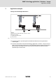
400 Technology applications | Actuator – torque Application example 3 Application example Conveyor drive with adjustable tension Slave Master i1 d1 i2 v d2 M F n Master o Slave with technology application "actuator – torque" p System bus (CAN) v = speed of the material path F = tensile stress [3-1] Example: Conveyor drive with adjustable tension r The master drive is operated speed-controlled and determines the speed of the material path.
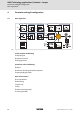
9400 Technology applications | Actuator – torque Parameter setting & configuration Basic signal flow 4 Parameter setting & configuration 4.1 Basic signal flow Torque setpoint DI3 Gain Basic drive functions Invert setpoint Ramp generator DI1 LS_Quickstop n IN AIN1 0 2 1 OUT LS_Stop n STOP 8 t LS_Brake internal status machine 9 t : Speed limit DI4 Offset Selection Ramp generator 3 4 5 OUT 1 2 15 6 DI6 Fixed setpoints % % LS_Torque...
9400 Technology applications | Actuator – torque Parameter setting & configuration Assignment of the I/O terminals 4.2 Assignment of the I/O terminals 4.2.1 Setpoint and control signals The following tables contain the Lenze assignment of the analog and digital inputs for the "Actuating drive - torque" technology application.
9400 Technology applications | Actuator – torque Parameter setting & configuration Assignment of the I/O terminals 4.2.2 Actual value and status signals The following tables contain the Lenze assignment of the analog and digital outputs for the "Actuating drive - torque" technology application. r The default signal configuration if required can be easily changed by parameterising the multiplexer parameters assigned.
9400 Technology applications | Actuator – torque Parameter setting & configuration Machine parameters 4.3 Machine parameters The machine parameters describe e.g. the motor end of the mechanics used. M The setting of the machine parameters in the »Engineer» is carried out on the Application parameters tab in the dialog level Overview Drive interface .
9400 Technology applications | Actuator – torque Parameter setting & configuration Torque setpoint conditioning 4.4 Torque setpoint conditioning Torque setpoint Gain DI3 Invert setpoint Ramp generator IN AIN1 OUT DI2 LS_Torque...
9400 Technology applications | Actuator – torque Parameter setting & configuration Torque setpoint conditioning 4.4.1 Setpoint inversion Torque setpoint Gain DI3 Invert setpoint Ramp generator DI2 IN AIN1 LS_Torque... Torque setpoint OUT M Status machine (basic drive functions) M v F [4-3] Setpoint inversion (schematic diagram) Via the digital input DI3 the effective direction of the (bipolar) setpoint can be inverted, if required.
9400 Technology applications | Actuator – torque Parameter setting & configuration Speed limit value conditioning 4.5 Speed limit value conditioning Speed limit DI4 Offset Selection Ramp generator IN AIN2 OUT DI2 LS_Torque... Torque setpoint M Status machine (basic drive functions) M Fixed setpoints [4-5] 1 2 % % v 15 % F Speed limit value conditioning (schematic diagram) The speed limit value is defined in the Lenze setting via the analog input 2.
9400 Technology applications | Actuator – torque Parameter setting & configuration Speed limit value conditioning 4.5.1 Change-over to fixed setpoint Speed limit DI4 Offset Selection Ramp generator IN AIN2 OUT DI2 LS_Torque... Torque setpoint M Status machine (basic drive functions) M Fixed setpoints [4-6] 1 2 % % v 15 % F Additional offset for the speed limit value (schematic diagram) Via the digital input DI4 a change-over to a parameterisable fixed setpoint can take place.
9400 Technology applications | Actuator – torque Parameter setting & configuration Speed limit value conditioning 4.5.2 Speed ramp generator Speed limit DI4 Offset Selection Ramp generator IN AIN2 OUT DI2 LS_Torque...
9400 Technology applications | Actuator – torque Parameter setting & configuration Speed limit value conditioning Use of further ramp parameter sets If required, 15 further ramp parameter sets can be parameterised. For the selection of the ramp parameter sets 1 ... 15, the selection inputs are to be assigned with the corresponding signals. The selection of the ramp parameter sets is carried out in a binary coded manner.
9400 Technology applications | Actuator – torque Parameter setting & configuration Torque follower 4.6 Torque follower Torque setpoint DI3 Gain Basic drive functions Invert setpoint Ramp generator DI1 LS_Quickstop n IN AIN1 LS_Stop n STOP LS_Brake internal status machine OUT t t Speed limit DI4 Offset Selection Ramp generator DI2 IN AIN2 LS_Torque...
9400 Technology applications | Actuator – torque Parameter setting & configuration Manual jog 4.7 Manual jog Torque setpoint DI3 Gain Basic drive functions Invert setpoint Ramp generator DI1 LS_Quickstop n IN AIN1 LS_Stop n STOP LS_Brake internal status machine OUT t t Speed limit DI4 Offset Selection Ramp generator DI2 IN AIN2 LS_Torque...
9400 Technology applications | Actuator – torque Parameter setting & configuration Quick stop 4.8 Quick stop Basic drive functions DI1 LS_Quickstop n LS_Stop n STOP internal status machine t DI2 Status machine (basic drive functions) M LS_ManualJog ç è è DI7 ç DI8 t LS_Torque...
9400 Technology applications | Actuator – torque Parameter setting & configuration Limiter 4.9 Limiter Basic drive functions DI1 LS_Quickstop n LS_Stop n STOP internal status machine t DI2 Status machine (basic drive functions) M LS_ManualJog ç è è DI7 ç DI8 t LS_Torque... Torque setpoint DI6 LS_Brake M The basic function "Limiter", where applicable, by means of limit switches monitors travel range limits.
9400 Technology applications | Actuator – torque Parameter setting & configuration Brake control 4.10 Brake control Basic drive functions DI1 LS_Quickstop n LS_Stop n STOP internal status machine t DI2 LS_ManualJog ç è è DI7 ç DI8 Status machine (basic drive functions) M The basic function "Brake control" serves to the wear free control and monitoring of a holding brake. In the simplest case, an optionally available brake module is used. t LS_Torque...
9400 Technology applications | Actuator – torque Parameter setting & configuration Brake control Control/setpoint inputs of the function Lenze setting Signal configuration Control/setpoint input (Multiplexer parameters) FALSE Open brake (release) C03165/1 FALSE Activate starting torque 2 C03165/2 FALSE Keep open brake at standstill C03165/3 FALSE Brake status signal C03165/4 FALSE Activate brake test C03165/5 FALSE Grind brake C03165/6 0 % Additional torque EDS94TA10020xxxx
9400 Technology applications | Actuator – torque Parameter setting & configuration Signal configuration 4.11 Signal configuration 4.11.1 Drive and motor interface If required, the preset signal configuration of the control and setpoint inputs of the drive and motor interface can be easily reconfigured per parameter setting of the assigned multiplexer parameters.
9400 Technology applications | Actuator – torque Parameter setting & configuration Signal configuration 4.11.2 Output ports If required, the preset signal configuration of the output ports can be easily reconfigured per parameter setting of the assigned multiplexer parameters. Output port "LPortAxisOut1" The output port LPortAxisOut1 is intended for the connection with a following axis.
9400 Technology applications | Actuator – torque Parameter setting & configuration Signal configuration Output port "LPortStatus1" The output port LPortStatus1 is intended for the connection with a higher-level control.
9400 Technology applications | Actuator – torque Parameter setting & configuration Application error messages 4.12 Application error messages For the output of application-specific error messages an FB instance L_DevApplErr1 of the function block L_DevApplErr is available. r Via the 8 boolean inputs up to 8 different application error messages with parameterisable module ID, error ID and error response can be activated by the application.
9400 Technology applications | Actuator – torque Parameter setting & configuration Parameterisable function blocks 4.13 Parameterisable function blocks This subchapter lists all relevant parameterisable function blocks of the technology application and the corresponding parameters in alphabetical order. 4.13.1 L_DevApplErr1 Is an instance of Function L_DevApplErr Error handling Application error messages (C 29) Parameter Possible settings C03900 980 C03901/1...
9400 Technology applications | Actuator – torque Parameter setting & configuration Parameterisable function blocks Parameter Possible settings C03512/1...15 0.000 s 1000.000 Acceleration time 1...15 • Initialisation: 0.000 s C03513/1...15 0.000 s 1000.000 Deceleration time 1...15 • Initialisation: 0.000 s C03514/1...15 0.000 s 1000.000 S-ramp time 1...15 • Initialisation: 0.
9400 Technology applications | Actuator – torque Parameter setting & configuration Parameterisable function blocks Parameter Possible settings Information C03539/2 Hold setpoint output • Display of input signal bHoldOutput. 0 Setpoint output enabled 1 Hold setpoint output C03539/3 Activate stop • Display of input signal bStop. 0 Stop not active 1 Stop requested C03539/4...7 Activate fixed setpoint 1 ... 8 • Display of input signals bJog1 ... bJog8.
)(('%$&. Your opinion is important to us These instructions were created to the best of our knowledge and belief to give you the best possible support for handling our product. If you have suggestions for improvement, please e-mail us to: feedback-docu@Lenze.de Thank you for your support.
© 10/2008 ) Lenze Automation GmbH Grünstraße 36 D-40667 Meerbusch Germany Service +49 (0)21 32 / 99 04-0 Lenze Service GmbH Breslauer Straße 3 D-32699 Extertal Germany 00 80 00 / 24 4 68 77 (24 h helpline) ¬ +49 (0)21 32 / 7 21 90 ¬ +49 (0)51 54 / 82-11 12 | Lenze@Lenze.de | Service@Lenze.de Þ www.Lenze.com EDS94TA10020xxxx 13277845 EN 1.