Automation Systems Controller-based Automation 13462098 Ä.
Contents ________________________________________________________________ 1 1.1 1.2 1.3 1.
Contents ________________________________________________________________ 8 8.1 8.2 8.3 8.4 8.5 8.6 8.7 8.8 8.9 8.12 8.13 8.14 8.
Contents ________________________________________________________________ 10 Mixed operation of CANopen and EtherCAT _ _ _ _ _ _ _ _ _ _ _ _ _ _ _ _ _ _ _ _ _ _ _ _ _ _ _ _ _ _ 92 11 SM3_Drive_Lenze.
1 About this documentation ________________________________________________________________ 1 About this documentation This documentation ... • contains detailed information about the commissioning, configuration, and diagnostics of the CANopen® bus system as part of the Lenze automation system Controller-based Automation. • is part of the "Controller-based Automation" manual collection.
1 About this documentation ________________________________________________________________ More technical documentation for Lenze components Further information on Lenze products which can be used in conjunction with Controller-based Automation can be found in the following sets of documentation: Mounting & wiring Symbols: Mounting instructions • Controller • Communication cards (MC-xxx) • I/O system 1000 (EPM-Sxxx) • Inverter, Servo Drives • Communication modules Printed documentation Online h
1 About this documentation 1.1 Document history ________________________________________________________________ 1.1 Document history Version 7 Description 1.0 06/2008 TD17 First edition 2.0 09/2008 TD17 Chapter "Mixed operation of CANopen and EtherCAT" ( 92) added. 3.0 06/2009 TD17 General revision 4.0 10/2009 TD17 General revision 5.0 10/2010 TD17 Commissioning and configuration with the Lenze »PLC Designer« V3.x 5.1 03/2011 TD17 5.
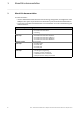
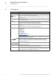
1 About this documentation 1.2 Conventions used ________________________________________________________________ 1.2 Conventions used This documentation uses the following conventions to distinguish different types of information: Type of information Identification Examples/notes Numbers Decimal Decimal separator Hexadecimal Binary • Nibble Normal spelling Point 0x[0 ... 9, A ... F] 0b[0, 1] Example: 1234 In general, the decimal point is used. Example: 1234.
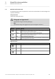
1 About this documentation 1.3 Terminology used ________________________________________________________________ 1.3 Terminology used Term Meaning CAN CAN (Controller Area Network) is an asynchronous, serial fieldbus system. CANopen® is a communication protocol based on CAN. The Lenze system bus (CAN on board) operates with a subset of this communication protocol. CANopen® is a registered Community Trade Mark of the CAN User Organisation CiA® (CAN in Automation e. V.).
1 About this documentation 1.4 Definition of the notes used ________________________________________________________________ 1.
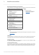
2 Safety instructions ________________________________________________________________ 2 Safety instructions Observe the following safety instructions if you want to commission an inverter or a system with the Lenze Controller. Read the documentation supplied with the system components carefully before you start commissioning the devices and the Lenze Controller! Danger! The system manual contains safety instructions which must be observed! Risk of injury There is risk of injury by ...
3 Controller-based Automation: Central motion control ________________________________________________________________ 3 Controller-based Automation: Central motion control The Lenze automation system "Controller-based Automation" serves to create complex automation solutions with central motion control. Here, the Controller is the control centre of the system.
3 Controller-based Automation: Central motion control ________________________________________________________________ Lenze provides especially coordinated system components: • Engineering software The Lenze Engineering tools ( 19) on your Engineering PC (Windows operating system ) serve to parameterise, configure and diagnose the system. The Engineering PC communicates with the Controller via Ethernet.
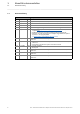
3 Controller-based Automation: Central motion control ________________________________________________________________ Fieldbus communication The Lenze Controllers have different interfaces for fieldbus communication: Area Cabinet Controller c300 3221 C 3231 C Panel Controller 3241 C p300 p500 Interfaces (on board) Ethernet 1 2 1 2 EtherCAT 1 1) 1 1 1) 1 CANopen 1 2) - 1 2) - Optional interfaces (communication cards) CANopen MC-CAN2 - - PROFIBUS master MC-PBM - - PR
4 System bus (CAN) / CANopen ________________________________________________________________ 4 System bus (CAN) / CANopen The control technology based on CANopen allows for the integration of all Lenze device series provided with the Lenze system bus (CAN on board). In order to extend the existing limits of the CAN bus, several CAN lines synchronised with each other can be used. The number of CAN lines available depends on the equipment of the Lenze Controller in each case.
4 System bus (CAN) / CANopen 4.1 CANopen (Logic) / CANopen (Motion) ________________________________________________________________ 4.
4 System bus (CAN) / CANopen 4.2 Field devices ________________________________________________________________ 4.
4 System bus (CAN) / CANopen 4.3 CANopen hardware for Lenze Controllers ________________________________________________________________ 4.3 CANopen hardware for Lenze Controllers Communication card MC-CAN2 The MC-CAN2 communication card serves to connect a Lenze Controller to the CAN bus system. The card provides two independent bus lines.
4 System bus (CAN) / CANopen 4.4 Lenze Engineering tools ________________________________________________________________ 4.4 Lenze Engineering tools The Lenze Engineering tools enable the configuration and operation of controller-based Lenze automation systems according to individual requirements. Use the corresponding Engineering tool applicable to the field device. »EASY Navigator« The »EASY Navigator« provides an overview of the Lenze Engineering software installed on the Engineering PC.
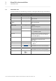
5 Technical data 5.1 General data ________________________________________________________________ 5 Technical data 5.1 General data Area Values Communication profile CANopen (DS301, V4.02) Standards CAN, ISO 11898 / EN 50325-4 Network topology Line, terminated at both ends with 120 (e.g. terminated with Sub-D plug of type EWZ0046) Max. number of nodes 127 Adjustable node addresses 1 ...
5 Technical data 5.2 Technical data of the MC-CAN2 communication card ________________________________________________________________ 5.2 Technical data of the MC-CAN2 communication card Area Values Type within the network Master or slave Max. number of nodes 63 Max. baud rate 1000 kbps Bus length See chapter "Bus cable length" ( 22) Connection SUB-D, 9-pole plug Connection of CAN bus (SUB-D, 9-pole plug) View 5.
5 Technical data 5.4 Bus cable length ________________________________________________________________ 5.4 Bus cable length 5.4.1 Note! • It is absolutely necessary to comply with the permissible cable lengths. • Observe the reduction of the total cable length due to the signal delay of the repeater. Use of repeaters ( 23) • If the total cable lengths of the nodes are different at the same baud rate, the smaller value must be used to determine the max. cable length.
5 Technical data 5.4 Bus cable length ________________________________________________________________ 5.4.3 Use of repeaters Compare the values from the tables Total cable length ( 22) and Segment cable length ( 22). If the detected segment cable length is smaller than the total cable length to be achieved, repeaters must be used. Example: Detecting cable lengths / number of repeaters Given: Cable cross-section 0.
5 Technical data 5.4 Bus cable length ________________________________________________________________ Example: Check use of repeater Given: Baud rate 125 kbps Cable cross-section 0.5 mm2 Number of nodes 28 Cable length 450 m Test step Cable length See table ... 1 Total cable length at 125 kbps: 630 m Total cable length ( 22) 2 Segment cable length for 28 nodes and a cable cross- 360 m section of 0.
6 Planning the CANopen network ________________________________________________________________ 6 Planning the CANopen network Create an overview screen of the planned CANopen network with all field devices to be implemented. Start with the Lenze Controller and arrange the other field devices below it (see Example of an overview screen ( 27)).
6 Planning the CANopen network 6.1 COB-IDs acc. to DS301 ________________________________________________________________ 6.1 Please observe ... the device-specific information on the CAN configuration in the documentation for the field devices to be implemented. COB-IDs acc.
6 Planning the CANopen network 6.2 Example of an overview screen ________________________________________________________________ 6.2 Example of an overview screen The illustration shows you an example of an overview screen for planning a CANopen network: [6-1] 27 Example of an overview screen for designing a CANopen network Lenze · Controller-based Automation · CANopen® Communication Manual · DMS 6.
6 Planning the CANopen network 6.3 Device specifications of the field devices ________________________________________________________________ 6.3 Device specifications of the field devices When planning your CANopen network, consider the device specifications of the implemented field devices.
6 Planning the CANopen network 6.3 Device specifications of the field devices ________________________________________________________________ 6.3.1 Special features of the 9400 Servo Drives • The parameter data channel 1 is always active. • The optional parameter data channels 2 ... 10 can be activated via the subcodes of the codes Cxx372 and Cxx373.
6 Planning the CANopen network 6.3 Device specifications of the field devices ________________________________________________________________ 6.3.
6 Planning the CANopen network 6.3 Device specifications of the field devices ________________________________________________________________ 6.3.
6 Planning the CANopen network 6.4 Special case: Delayed switch-on of one or more slaves ________________________________________________________________ 6.4 Special case: Delayed switch-on of one or more slaves When the master is started, all slave devices must be switched on. If this is not the case, a special procedure must be carried out for the following cases: A. One or more slaves are switched on after the master starting process.
7 Preparing the field devices 7.1 Installing field devices ________________________________________________________________ 7 Preparing the field devices 7.1 Installing field devices Install the field devices according to the data given in the device-specific mounting instructions. Make sure that ... • the CANopen installation complies with your overview screen. • all devices are supported by the control technology system on the Logic bus and Motion bus.
7 Preparing the field devices 7.3 Connecting the Engineering PC to the Lenze Controller ________________________________________________________________ 7.3 Connecting the Engineering PC to the Lenze Controller To commission the field devices, an online connection is required between the Engineering PC and the field device.
7 Preparing the field devices 7.3 Connecting the Engineering PC to the Lenze Controller ________________________________________________________________ The communication speed with the field devices, when being commissioned, mainly depends on whether the Lenze Controller is currently running or is stopped. In the latter case, the total bandwidth of the fieldbus is provided to the gateway so that the speed advantage in the case of direct coupling would only be marginal.
8 Commissioning of the CANopen Logic bus 8.1 Sample projects (Application Samples) ________________________________________________________________ 8 Commissioning of the CANopen Logic bus This chapter provides information for the commissioning of the CANopen Logic field devices in the Lenze automation system. Depending on the field devices used, the following Lenze Engineering tools ( 19) are required: • »EASY Starter« • »Engineer« • »PLC Designer« 8.
8 Commissioning of the CANopen Logic bus 8.2 Overview of the commissioning steps ________________________________________________________________ 8.2 Overview of the commissioning steps Step Activity Lenze Engineering tool to be used 1. Create a project folder ( 38) 2. Commissioning the field devices ( 39) »Engineer« / »EASY Starter« »PLC Designer« 3. Creating a PLC program with a target system (Logic) ( 40) 4. Configuring the communication parameters ( 42) 5.
8 Commissioning of the CANopen Logic bus 8.3 Create a project folder ________________________________________________________________ 8.3 Create a project folder Create a project folder on the Engineering PC.
8 Commissioning of the CANopen Logic bus 8.4 Commissioning the field devices ________________________________________________________________ 8.4 Commissioning the field devices Parameterise the Lenze field devices connected to the CANopen network by means of the »Engineer« or »EASY Starter«. CANopen is exclusively configured by means of the »PLC Designer«. CANopen settings of the field devices which have possibly been carried out with the »Engineer«/ »EASY Starter« are overwritten.
8 Commissioning of the CANopen Logic bus 8.5 Creating a PLC program with a target system (Logic) ________________________________________________________________ 8.5 Creating a PLC program with a target system (Logic) The »PLC Designer« serves to model the network topology in the control configuration. Tip! The »PLC Designer« can be used to configure CANopen nodes and nodes on other fieldbus systems.
8 Commissioning of the CANopen Logic bus 8.5 Creating a PLC program with a target system (Logic) ________________________________________________________________ 4. Go to the Standard project dialog window and select the target system in the selection field: Device Lenze Logic Controller For actuating controllers that execute simple movements, have no Motion functionality, or are controlled via pure PLC functionalities.
8 Commissioning of the CANopen Logic bus 8.6 Configuring the communication parameters ________________________________________________________________ 8.6 Configuring the communication parameters Set the communication parameters to establish an online connection to the Lenze Controller later on. How to configure the communication parameters 1. Go to the Communication settings tab of the target system (device) and click the gateway button.
8 Commissioning of the CANopen Logic bus 8.6 Configuring the communication parameters ________________________________________________________________ 3. Click the Scan network button. 4. Select the suitable means of the controller for the IP address entered under 2. and activate it by Set active path button (or by double-click). 5.
8 Commissioning of the CANopen Logic bus 8.7 Importing missing devices / device description files ________________________________________________________________ 8.7 Importing missing devices / device description files The device description file contains the data of the fieldbus peripherals required for the master control. This file is required to program the control system.
8 Commissioning of the CANopen Logic bus 8.8 Creating a control configuration (adding field devices) ________________________________________________________________ 8.8 Creating a control configuration (adding field devices) Note! The configuration of a Lenze Controller in a CANopen network must be created in the »PLC Designer«, because the complete configuration is written to the connected slaves when a controller is started. This process overwrites the previous slave settings.
8 Commissioning of the CANopen Logic bus 8.8 Creating a control configuration (adding field devices) ________________________________________________________________ 2. Use the CANbus tab to set the baud rate. Note! The baud rate set in the »PLC Designer« overwrites the baud rate set for the field devices via »Engineer« or »EASY Starter«. Always set the same baud rate for all nodes in a CANopen network. 3. Use the Add Device to add the configuration.
8 Commissioning of the CANopen Logic bus 8.8 Creating a control configuration (adding field devices) ________________________________________________________________ 4. Use the CANopen_Manager tab to set the parameters for Sync generation. Sync generation is required if ... • at least one PDO with sync-controlled processing is used on the bus; • the applications are to run in a clock-synchronised manner on several field devices; • Motion devices are to be operated on the fieldbus.
8 Commissioning of the CANopen Logic bus 8.8 Creating a control configuration (adding field devices) ________________________________________________________________ 5. Use the command (master). Add Device to add a Logic device (slave) to the CANopen_Manager Select a field device from the selection list. You can only select devices the CANopen device description files of which have been imported in the »PLC Designer«.
8 Commissioning of the CANopen Logic bus 8.8 Creating a control configuration (adding field devices) ________________________________________________________________ 7. Give the inserted slaves suitable names (e.g. "Drive_vertical"). The names must … • only contain the characters "A ... Z", "a ... z", "0 ... 9" or "_"; • not begin with a digit. You can enter a name by clicking the element. Example: 49 Lenze · Controller-based Automation · CANopen® Communication Manual · DMS 6.
8 Commissioning of the CANopen Logic bus 8.9 Setting of CAN parameters and PDO mapping ________________________________________________________________ 8.9 Setting of CAN parameters and PDO mapping Set the CAN parameter and the PDO mapping for each Logic device connected to the bus. How to set CAN parameters and CAN mapping: 1. Go to the CANopen Remote Device tab of the respective slave.
8 Commissioning of the CANopen Logic bus 8.9 Setting of CAN parameters and PDO mapping ________________________________________________________________ 2. Go to the PDO Mapping tab. The default setting for PDO mapping is a position mapping. This mapping can be changed manually (by ticking). Due to the limited bandwidth of the CAN bus, this is only useful in special cases. The default PDO properties, too, are useful default settings and should not be changed.
8 Commissioning of the CANopen Logic bus 8.9 Setting of CAN parameters and PDO mapping ________________________________________________________________ 3. The selection of a special bus cycle task on the CANopen I/O Mapping tab of the CANopen manager is not essential.
8 Commissioning of the CANopen Logic bus 8.9 Setting of CAN parameters and PDO mapping ________________________________________________________________ 8.9.1 Cross communication between the slaves With control via the CAN bus, cross communication between the slaves is possible. For this purpose, you must configure the CAN communication and the PDO mapping in the »Engineer« and write it to the controllers.
8 Commissioning of the CANopen Logic bus 8.9 Setting of CAN parameters and PDO mapping ________________________________________________________________ 8.9.2 Special features of the I/O system 1000 (EPM-Sxxx) Note! Before adding I/O modules beneath an EPM-S110 »PLC Designer«head station in the , the head station tab must be closed. If the I/O 1000 modules are added when the head station tab is open, there will not be shown any I/O image for the modules.
8 Commissioning of the CANopen Logic bus 8.9 Setting of CAN parameters and PDO mapping ________________________________________________________________ 6. Add the PDO configuration for the counter discs. The following example uses a receive PDO and a mapping element to describe the basic configuration process. Proceed accordingly for configuring the send PDOs ("Send PDO Mapping" tab). A) Use the Add PDO button and add the receive PDO.
8 Commissioning of the CANopen Logic bus 8.9 Setting of CAN parameters and PDO mapping ________________________________________________________________ B) Manually create the mapping of the new PDOs. • Select PDO and click Add Mapping. • Select the corresponding settings in the dialog box that appears. Note! If Autoconfig. PDO Mapping (see step 3) is reactivated after adding the manual configuration, the entire configuration that has been added manually will be deleted.
8 Commissioning of the CANopen Logic bus 8.10 Creating the program code for controlling the Logic field device ________________________________________________________________ 8.10 Creating the program code for controlling the Logic field device Note! All program blocks which are operated with an SDO communication must be called up in the same Logic task. Otherwise, jobs will get lost.
8 Commissioning of the CANopen Logic bus 8.10 Creating the program code for controlling the Logic field device ________________________________________________________________ How to create the program code: 1. Create the program code for controlling the field device. The device must be used in the program code in order that the SDO initialisation takes place. If other field devices are added to the control configuration, this may change the object addresses (%Qxx, %Ixx) of the existing variables.
8 Commissioning of the CANopen Logic bus 8.11 Preparing the restart ________________________________________________________________ 8.11 Preparing the restart In the control technology system you can use the Lenze Controller to transmit the complete parameter setting via SDO initialisation to the field devices when the machine is switched on. According to DS301, the Lenze Controller always initialises the CAN parameters of the field devices.
8 Commissioning of the CANopen Logic bus 8.11 Preparing the restart ________________________________________________________________ 8.11.1 Special features of the 9400 Servo Drives HighLine Servo Drives 9400 are not purely parameterisable devices. They require an application download, where several files are transmitted to the memory module. To put a Servo Drive 9400 into operation, you can: • plug on the memory module. • transmit the application using the »Engineer«.
8 Commissioning of the CANopen Logic bus 8.11 Preparing the restart ________________________________________________________________ 8.11.3 Special features of the I/O system 1000 (EPM-Sxxx) There are different possibilities for restarting the I/O system: • Automatically • Automatically with factory adjustment • Using the »Engineer« For the corresponding settings, first tick the "Expert settings" on the CANopen Remote Device tab. 8.11.3.
8 Commissioning of the CANopen Logic bus 8.11 Preparing the restart ________________________________________________________________ 8.11.3.2 Automatic restart with factory adjustment Settings for automatic initialisation with factory adjustment by the Lenze Controller: 1. Enter all desired parameter values under the All parameters tab. 2. Tick "Default settings" under the CANopen Remote Device tab. When the I/O system has been replaced 1.
8 Commissioning of the CANopen Logic bus 8.11 Preparing the restart ________________________________________________________________ 8.11.3.3 Restart with the »Engineer« Preconditions • You have implemented the I/O system successfully into the PLC program. • You have parameterised some CANopen indexes of the I/O system using the »Engineer«.
8 Commissioning of the CANopen Logic bus 8.12 Compiling the PLC program code ________________________________________________________________ 8.12 Compiling the PLC program code In order to compile the PLC program code, select the menu command Build Build, or press function key . • If errors occur during translation, they can be located and corrected on the basis of the »PLC Designer« error messages. Then re-translate the program code.
9 Commissioning of the CANopen Motion bus ________________________________________________________________ 9 Commissioning of the CANopen Motion bus This chapter provides information on commissioning the CANopen Motion field devices in the Lenze automation system. The commissioning of a Motion device does not differ fundamentally from the commissioning of a Logic device. Below a Motion device, an additional "SoftMotion" node is displayed in the device tree. Via this node, further settings must be made.
9 Commissioning of the CANopen Motion bus 9.1 Sample projects (Application Samples) ________________________________________________________________ 9.1 Sample projects (Application Samples) There already exist sample projects (device application + PLC program) for commissioning of Lenze Controllers. The Lenze sample projects can be found in the MS Windows start menu under: Start All programs Lenze AppSamples ...
9 Commissioning of the CANopen Motion bus 9.2 Overview of the commissioning steps ________________________________________________________________ 9.2 Overview of the commissioning steps Step Activity Lenze Engineering tools to be used 1. Create a project folder ( 68) 2. Commissioning the field devices ( 69) »Engineer« / »EASY Starter« »PLC Designer« 3. Creating a PLC program with target system (Motion) ( 70) 4. Configuring the communication parameters ( 72) 5.
9 Commissioning of the CANopen Motion bus 9.3 Create a project folder ________________________________________________________________ 9.3 Create a project folder Create a project folder on the Engineering PC.
9 Commissioning of the CANopen Motion bus 9.4 Commissioning the field devices ________________________________________________________________ 9.4 Commissioning the field devices Parameterise the Lenze field devices connected to the CANopen network by means of the »Engineer« or »EASY Starter«. Die CANopenis exclusively configured using the »PLC Designer«. CANopen settings of the field devices which have possibly been carried out with the »Engineer«/ »EASY Starter« are overwritten.
9 Commissioning of the CANopen Motion bus 9.5 Creating a PLC program with target system (Motion) ________________________________________________________________ 9.5 Creating a PLC program with target system (Motion) The »PLC Designer« serves to model the network topology in the control configuration. Tip! The »PLC Designer« can be used to configure CANopen nodes and nodes on other fieldbus systems.
9 Commissioning of the CANopen Motion bus 9.5 Creating a PLC program with target system (Motion) ________________________________________________________________ 4. Go to the Standard project dialog window and select the target system in the selection field: Device Lenze Motion Controller For actuating controllers that, e.g. execute synchronised movements or have a Motion functionality and are used for PLCopen libraries.
9 Commissioning of the CANopen Motion bus 9.6 Configuring the communication parameters ________________________________________________________________ 9.6 Configuring the communication parameters Set the communication parameters to establish an online connection to the Lenze Controller later on. How to configure the communication parameters 1. Go to the Communication settings tab of the target system (device) and click the gateway button.
9 Commissioning of the CANopen Motion bus 9.6 Configuring the communication parameters ________________________________________________________________ 3. Click the Scan network button. 4. Select the suitable means of the controller for the IP address entered under 2. and activate it by Set active path button (or by double-click). 5.
9 Commissioning of the CANopen Motion bus 9.7 Creating a Motion task ________________________________________________________________ 9.7 Creating a Motion task How to create a Motion task: 1. Go Task configuration in the configuration tree. 2. Create a new task with the Add Object command. Assign a sensible task name (e.g. "MotionTask"). 3. Enter a reasonable cycle time in milliseconds in the Interval input field.
9 Commissioning of the CANopen Motion bus 9.7 Creating a Motion task ________________________________________________________________ 4. Go to Application in the configuration tree. 5. Use the Add Object command to create a new program block (POU) in the application. Assign a reasonable POU name (e.g. "Motion_PRG"). . 75 Lenze · Controller-based Automation · CANopen® Communication Manual · DMS 6.
9 Commissioning of the CANopen Motion bus 9.7 Creating a Motion task ________________________________________________________________ 6. Add this program call to the task using the Add POU command. Lenze · Controller-based Automation · CANopen® Communication Manual · DMS 6.
9 Commissioning of the CANopen Motion bus 9.7 Creating a Motion task ________________________________________________________________ The following task configuration is caused: 77 Lenze · Controller-based Automation · CANopen® Communication Manual · DMS 6.
9 Commissioning of the CANopen Motion bus 9.8 Creating a control configuration ________________________________________________________________ 9.8 Creating a control configuration Note! The configuration of a Lenze Controller in a CANopen network must be created in the »PLC Designer«, because the complete configuration is written to the connected slaves when a controller is started. This process overwrites the previous slave settings.
9 Commissioning of the CANopen Motion bus 9.8 Creating a control configuration ________________________________________________________________ 2. Use the CANbus tab to set the baud rate. Note! The baud rate set in the »PLC Designer« overwrites the baud rate set for the field devices via »WebConfig« or »Engineer«. Always set the same baud rate for all nodes in a CANopen network. 3. Use the command configuration.
9 Commissioning of the CANopen Motion bus 9.8 Creating a control configuration ________________________________________________________________ 4. Use the CANopen Manager tab to set the parameters for Sync generation. Note! To prevent the sync telegram from jittering, all Motion phases must be assigned to the same task. Sync generation is required if ...
9 Commissioning of the CANopen Motion bus 9.8 Creating a control configuration ________________________________________________________________ 5. Use the command Add Device to add a Motion device (slave) to the CANopen_Manager (master). Select a field device from the selection list. For EDS files created in the »Engineer«, the field device appears in the selection list with the same name as during the export of the EDS file in the »Engineer«, extended by the name of the interface and device type. 6.
9 Commissioning of the CANopen Motion bus 9.9 Parallel operation of two synchronised CAN buses ________________________________________________________________ 9.9 Parallel operation of two synchronised CAN buses The MC-CAN2 communication card is provided with two CAN interfaces. Thus, basically two CAN buses can be operated independently of each other. The two buses can also be operated in a synccontrolled manner.
9 Commissioning of the CANopen Motion bus 9.9 Parallel operation of two synchronised CAN buses ________________________________________________________________ In the device tree of the »PLC Designer« project, the CAN bus which works via CAN interface 1 (CAN1) must be first: 83 Lenze · Controller-based Automation · CANopen® Communication Manual · DMS 6.
9 Commissioning of the CANopen Motion bus 9.10 Setting SoftMotion parameters ________________________________________________________________ 9.10 Setting SoftMotion parameters Note! In the »PLC Designer«, the SoftMotion tabs are only available for field devices using a Motion application (e.g. Servo Drive 9400 Highline CiA 402). The SoftMotion parameters are to be set in relation to the application.
9 Commissioning of the CANopen Motion bus 9.10 Setting SoftMotion parameters ________________________________________________________________ How to set the SoftMotion parameters 1. Open the tab SoftMotion drive: Scaling/Mapping and adapt the conversion factors in the "Scaling" area. 85 Lenze · Controller-based Automation · CANopen® Communication Manual · DMS 6.
9 Commissioning of the CANopen Motion bus 9.10 Setting SoftMotion parameters ________________________________________________________________ 2. Open the tab SoftMotion drive: basic parameters and set the axis types and limitations. • Do not use the "virtual mode" setting. • Virtual axes are in the "SoftMotion General Drive Pool".
9 Commissioning of the CANopen Motion bus 9.11 Setting of CAN parameters and PDO mapping ________________________________________________________________ 9.11 Setting of CAN parameters and PDO mapping Set the CAN parameter and the PDO mapping for each Motion device connected to the bus. How to set CAN parameters and CAN mapping: 1. Go to the CANopen Remote Device tab of the respective slave.
9 Commissioning of the CANopen Motion bus 9.11 Setting of CAN parameters and PDO mapping ________________________________________________________________ 2. Go to the PDO Mapping tab. The default setting for PDO mapping is a position mapping. This mapping can be changed manually (by ticking). Due to the limited bandwidth of the CAN bus, this is only useful in special cases. The default PDO properties, too, are useful default settings and should not be changed.
9 Commissioning of the CANopen Motion bus 9.11 Setting of CAN parameters and PDO mapping ________________________________________________________________ 3. The selection of a special bus cycle task on the CANopen I/O Mapping tab of the CANopen manager is not essential.
9 Commissioning of the CANopen Motion bus 9.12 Creating the program code for controlling the Motion field device ________________________________________________________________ 9.12 Creating the program code for controlling the Motion field device This depends on the automation task, the use of PLCopen blocks or the CNC programming. Note! All SoftMotion function blocks, SoftMotion functions, and the read/write block parameters that access the SoftMotion devices (e.g.
9 Commissioning of the CANopen Motion bus 9.14 Compiling the PLC program code ________________________________________________________________ 9.14 Compiling the PLC program code In order to compile the PLC program code, select the menu command Build Build, or press function key . • If errors occur during translation, they can be located and corrected on the basis of the »PLC Designer« error messages. Then re-translate the program code.
10 Mixed operation of CANopen and EtherCAT ________________________________________________________________ 10 Mixed operation of CANopen and EtherCAT [10-1] Example: Mixed operation of EtherCAT with CANopen connected to a 3231 C controller with Servo-Inverter i700 and Servo Drives 9400 Within the Lenze Controller-based Automation, CANopen can be used in parallel to the EtherCAT bus system.
11 SM3_Drive_Lenze.lib function library ________________________________________________________________ 11 SM3_Drive_Lenze.lib function library The SM3_Drive_Lenze.lib function library supports the control of Motion devices (e.g. Servo Drives 9400 HighLine CiA 402). 93 Lenze · Controller-based Automation · CANopen® Communication Manual · DMS 6.
12 Restarting the CAN bus ________________________________________________________________ 12 Restarting the CAN bus During operation, the CAN bus may have to be restarted. This is e.g. required after serious disturbances such as a cable break. How to restart the CAN bus: 1. Activate the controller inhibit for the drive controllers. 2. Call the NMT function block (see below) from the CAA_CiA405.lib function library.
13 Defining the minimum cycle time of the PLC project 13.1 Determining the task utilisation of the application ________________________________________________________________ 13 Defining the minimum cycle time of the PLC project This chapter provides information on how to ... • Determining the task utilisation of the application ( 95) • Optimising the system ( 97) 13.
13 Defining the minimum cycle time of the PLC project 13.1 Determining the task utilisation of the application ________________________________________________________________ How to determine the task utilisation: Initial situation: A complete project, e.g. with a CANopen task and 2 lower priority tasks has been created. 1. For a first measurement of the task utilisation, set the cycle times of all cyclic tasks available in the PLC system "high" (e.g.
13 Defining the minimum cycle time of the PLC project 13.2 Optimising the system ________________________________________________________________ 13.2 Optimising the system How to optimise the system: 1. Use the menu command Online Login, or log in on the Lenze Controller with +. • For this, the PLC program must be error-free. • With the log-in, the fieldbus configuration and the PLC program are loaded into the Controller. 2. Check the task processing times. 3.
14 Diagnostics 14.1 Logbook of the Lenze Controller ________________________________________________________________ 14 Diagnostics The following diagnostic options are available: • Logbook of the Lenze Controller ( 98) • "Status" tab of the connected field devices ( 99) • Diagnostic codes ( 99) • System bus configurator of the »Engineer« ( 100) • »PCAN view« for diagnostic purposes ( 101) 14.
14 Diagnostics 14.2 "Status" tab of the connected field devices ________________________________________________________________ 14.2 "Status" tab of the connected field devices In the »PLC Designer«, there is a Status tab for each field device integrated into the control configuration. This tab can be used to call diagnostic information about the device. 14.3 Diagnostic codes In the »Engineer«, you can view the diagnostic codes of the Lenze field devices.
14 Diagnostics 14.4 System bus configurator of the »Engineer« ________________________________________________________________ 14.4 System bus configurator of the »Engineer« 1. First directly connect your notebook via the USB system bus adapter EMF2177IB to the CANopen bus. 2. Start the system bus configurator ... • via the Online button in the menu bar of the »Engineer« • or under "Start - Programs - Lenze - Communication" 3. Activate the USB system bus adapter (EMF2177IB). 4.
14 Diagnostics 14.5 »PCAN view« for diagnostic purposes ________________________________________________________________ 14.5 »PCAN view« for diagnostic purposes This chapter describes how to use the »PCAN view« program for diagnostics of your CANopen network. »PCAN view« is the basic version of the »PCAN explorer« program of PEAK System Technik GmbH. The program allows for simultaneous transmission and reception of CAN messages which can be sent manually and periodically.
14 Diagnostics 14.5 »PCAN view« for diagnostic purposes ________________________________________________________________ 4. Now the CAN telegrams are constantly displayed in the "Receive" and "Transmit" windows. On the basis of the IDs displayed and the IDs in your overview you can assign the telegrams to the devices.
14 Diagnostics 14.5 »PCAN view« for diagnostic purposes ________________________________________________________________ 14.5.2 Setting all CANopen nodes to the "Operational" status How to set all CANopen nodes to the "Operational" status: 1. Create the following CAN message under "New transmit message": 2. Select the CAN message in the "Transmit" window and press the once to send the CAN message. 103 Lenze · Controller-based Automation · CANopen® Communication Manual · DMS 6.
14 Diagnostics 14.6 Notes regarding the visualisation using »VisiWinNET« ________________________________________________________________ 14.6 Notes regarding the visualisation using »VisiWinNET« Problem description: For visualisation purposes a "VWGET" timer (1 second) is used to read a variable via the CAN bus (SDO) using the OPC server. If no nodes are connected and no information is returned, a time-out is generated.
15 Parameter reference ________________________________________________________________ 15 Parameter reference This chapter complements the parameter list in the online help of the Lenze Controller by the parameters of the MC-CAN2 communication card. These parameters ... • are for instance shown in the Lenze »WebConfig« (Engineering tool for web-based parameterisation); • are listed in numerically ascending order.
15 Parameter reference ________________________________________________________________ C1037 Parameter | Name: C1037 | Device: manufacturer Data type: VISIBLE_STRING Index: 23538 = 0x5BF2 Manufacturer of the card Read access Write access CINH PLC-STOP No transfer C1038 Parameter | Name: C1038 | Device: manufacturing date Data type: VISIBLE_STRING Index: 23537 = 0x5BF1 Manufacturing date of the card Read access Write access CINH PLC-STOP No transfer Lenze · Controller-based Aut
Index ________________________________________________________________ A Adding devices 45 Adding field devices 45 Application notes 10 Application Samples 36, 66 B Basic identifier - 8400 Inverter Drives 30 Basic identifier - 9400 Servo Drives 29 Basic identifier - I/O system 1000 (EPM-Sxxx) 31 Baud rates 20 Bus cable length 22 C C1031 | Device: Identification 105 C1032 | Device: Version 105 C1033 | Device: Name 105 C1034 | Device: Software version 105 C1035 | Device: Hardware version 105 C1036 | Device
Index ________________________________________________________________ G S General data 20 Safety instructions 10, 11 Sample projects (Application Samples) 36, 66 Screenshots 6 Segment cable length 22 Setting of CAN parameters (Logic devices) 50 Setting of CAN parameters (Motion devices) 87 Setting of PDO mapping (Logic devices) 50 Setting of PDO mapping (Motion devices) 87 Setting SoftMotion parameters 84 Setting Sync generation 47, 80 Setting the baud rate 33 Setting the node addresses 33 Signal propa
)(('%$&. 109 Your opinion is important to us These instructions were created to the best of our knowledge and belief to give you the best possible support for handling our product. Perhaps we have not succeeded in achieving this objective in every respect. If you have suggestions for improvement, please e-mail us to: feedback-docu@lenze.com Thank you very much for your support.
Controller-based Automation · CANopen® Communication Manual · KHBCANPCBAUTO · 13462098 · DMS 6.3 EN · 04/2014 · TD17 Lenze Automation GmbH Postfach 10 13 52, D-31763 Hameln Hans-Lenze-Straße 1, D-31855 Aerzen Germany +49 5154 82-0 +49 5154 82-2800 lenze@lenze.com www.lenze.com Service Lenze Service GmbH Breslauer Straße 3, D-32699 Extertal Germany 008000 24 46877 (24 h helpline) +49 5154 82-1112 service@lenze.