
Instructions Owner's manual


Electrical installation
Interfaces for peripheral devices
CAN port
6
29
Lenze ¯ BA_c300 ¯ 2.0
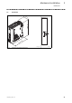
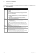
6.4.3 CAN port
Figure Connection Connection type Cable type
X5:
CAN bus connection
Pin 1: CAN−GND (CG)
Pin 2: CAN−LOW (LO)
Pin 3: not assigned
Pin 4: CAN−HIGH (HI)
Pin 5: not assigned
5−pole Phoenix
Combicon socket
CAN cable complying with
ISO 11898−2 with Phoenix
Combicon plug, MSTB 2.5 /
5−STF−5.8
EL100−011
Specification of the bus cable
We recommend using CAN cables complying with ISO 11898−2:
CAN cable complying with ISO 11898−2
Cable type Paired with shielding
Impedance 120 W (95 ... 140 W)
Cable resistance/cross−section
Cable length £ 300 m £ 70 mW/m / 0.25 0.34 mm
2
(AWG22)
Cable length 301 1000 m £ 40 mW/m / 0.5 mm
2
(AWG20)
Signal propagation delay £ 5 ns/m
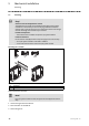
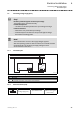
Connection plan
Stop!
Connect a 120 W terminating resistor to the first and last bus device.
CG
CAN
LO HI CG
CAN
LO HI CG
CAN
LO HI
RR
A
n
A
2
A
1
EL100−009
Fig. 6−2 Connection plan for the CAN bus
A1 Node 1
A2 Node 2
An Node n
CG CAN−GND
LO CAN−LOW
HI CAN−HIGH
R 120 W−bus terminating resistor
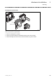
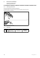
Shielding
EL100−033
Fig. 6−3 CAN cable shield connection via cable clamp in the control cabinet