
Instruction Manual

Lenze · Backup & Restore · Software Manual · DMS 1.3 EN · 04/2014 · TD17 35
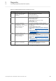
5Diagnostics
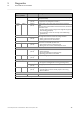
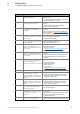
5.1 Status LEDs of the controllers
_ _ _ _ _ _ _ _ _ _ _ _ _ _ _ _ _ _ _ _ _ _ _ _ _ _ _ _ _ _ _ _ _ _ _ _ _ _ _ _ _ _ _ _ _ _ _ _ _ _ _ _ _ _ _ _ _ _ _ _ _ _ _ _
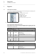
Yellow constant The supply voltage has fallen below the minimum value (voltage
failure/"Powerfail")
blinking
(2.0 Hz)
Status after switch-on/restart
(in preparation for c300/p300 controllers.)
green/
blue*
Yellow blinking
(0.5 Hz)
"System clock is not synchronised" (missing time information).
Note:
If the controller is switched off for more than two weeks, the set time
information is lost.
• The next starting sequence will generate a logbook entry (Power
LED is blinking green/blue).
• The current time must be set manually via the »WebConfig«
(parameter 91).
Only for Controller 3241 C: Battery pack (ACCU-PACK) is not fully charged.
The length of the dark bar indicates the charge condition:
• Battery pack almost dead: long dark bar
• Battery pack almost full: short dark bar
Green blinking
(5.0 Hz)
Only for Controller 3241 C: Error status of the battery pack (ACCU-PACK)
UPS function not available, possible cause:
• Interrupted connection to the battery pack
• Battery pack not connected, cable break/short circuit
Green Yellow blinking
(5.0 Hz)
Error
Red blinking
(5.0 Hz)
Error
• Fatal error (Abort)
• SD card not available/not inserted correctly
• Operating system licence not available
Green Red blinking
(5.0 Hz)
Mains switching required
Status 1 ("busy")
Green permanently lit Controller is running (operating status):
• PLC project is running (device is running, operating status)
blinking
(0.5 Hz)
Starting sequence of the controller is active
Green Yellow blinking
(0.5 Hz)
User action required:
• "Load PLC project": PLC was started, project is not running
• Remove USB stick
Status 2
--No function
* device-dependent LED colour: either green or blue
LED
Colour 1 / Colour 2
Interval Meaning