
Instruction Manual

5Diagnostics
5.1 Status LEDs of the controllers
34
Lenze · Backup & Restore · Software Manual · DMS 1.3 EN · 04/2014 · TD17
_ _ _ _ _ _ _ _ _ _ _ _ _ _ _ _ _ _ _ _ _ _ _ _ _ _ _ _ _ _ _ _ _ _ _ _ _ _ _ _ _ _ _ _ _ _ _ _ _ _ _ _ _ _ _ _ _ _ _ _ _ _ _ _
5 Diagnostics
5.1 Status LEDs of the controllers
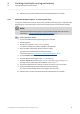
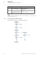
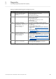
The controllers are equipped with LEDs that signal the current operating status. Depending on the
controller used, the colouring of the LEDs may vary.
[5-1] Example: Cabinet Controller 3200 C
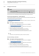
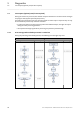
Specific signals during a »Backup & Restore« process
When a backup, restore, or update is carried out, the controllers show the respective status of the
»Backup & Restore« process by means of the Error and Status 1 LEDs. The signalling of the status
LEDs displays the respective status:
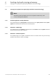
General information about the status LEDs of the controllers
• Power: green/blue*, yellow
• Error: green, red
• Status 1: green, yellow
• Status 2: no function
* device-dependent LED colour: either green or blue
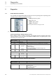
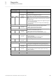
LED
Colour 1 / Colour 2
Interval Meaning
Error - during a »Backup & Restore«
Green permanently lit »Backup & Restore« process is completed, status: "Complete".
Red blinking
(5.0 Hz)
»Backup & Restore« process, status: "Error".
Possible causes:
• Fatal error (Abort)
• SD card not available/not inserted correctly in slot
Green Red blinking
(5.0 Hz)
Mains switching required
Status 1 ("busy") - during a »Backup & Restore«
Green blinking
(0.5 Hz)
»Backup & Restore« process active.
Green Yellow blinking
(0.5 Hz)
Remove USB stick
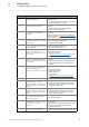
LED
Colour 1 / Colour 2
Interval Meaning
Power
green/blue* constant Starting sequence properly completed.
•No active error
• Controller is switched on
• Supply voltage OK