Engineering Tools Backup & Restore 13450101 Ä.
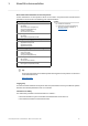
Contents ________________________________________________________________ 1 About this documentation . . . . . . . . . . . . . . . . . . . . . . . . . . . . . . . . . . . . . . . . . . . . . . . . . . . . . . . . . 4 1.1 Document history . . . . . . . . . . . . . . . . . . . . . . . . . . . . . . . . . . . . . . . . . . . . . . . . . . . . . . . . . . . . . . . 6 1.2 Conventions used . . . . . . . . . . . . . . . . . . . . . . . . . . . . . . . . . . . . . . . . . . . . . . . . . . . . . . . . . . .
Contents ________________________________________________________________ 5 6 Diagnostics. . . . . . . . . . . . . . . . . . . . . . . . . . . . . . . . . . . . . . . . . . . . . . . . . . . . . . . . . . . . . . . . . . . . . . . 34 5.1 Status LEDs of the controllers . . . . . . . . . . . . . . . . . . . . . . . . . . . . . . . . . . . . . . . . . . . . . . . . . . . . 34 5.2 Text outputs (optional panel/screen required) . . . . . . . . . . . . . . . . . . . . . . . . . . . . . . . . . . . . 5.2.
1 About this documentation ________________________________________________________________ 1 About this documentation This documentation contains information for carrying out »Backup & Restore« on the following Lenze Controllers: • Cabinet Controller as control system • Panel Controller as visualisation system Cabinet controllers with a DVI interface require an external Monitor Panel. This manual is part of the Controller-based Automation manual compilation.
1 About this documentation ________________________________________________________________ More technical documentation for Lenze components Further information on Lenze products which can be used in conjunction with Controller-based Automation can be found in the following sets of documentation: Mounting & wiring Mounting instructions • Controller • Communication cards (MC-xxx) • I/O system 1000 (EPM-Sxxx) • Inverter, Servo Drives • Communication modules Symbols: Printed documentation Online help
1 About this documentation 1.1 Document history ________________________________________________________________ 1.1 Document history Version 6 Description 1.0 08/2010 TD11 First edition on the Lenze automation system "Controller-based Automation" 3.x 1.1 06/2011 TD11 Revision on the Lenze automation system "Controller-based Automation" 3.1 1.2 08/2012 TD11 Revision on the Lenze automation system "Controller-based Automation" 3.3 1.
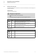
1 About this documentation 1.2 Conventions used ________________________________________________________________ 1.2 Conventions used This documentation uses the following conventions for highlighting different types of information: Type of information Identification Examples/notes Numbers Decimal Decimal separator Hexadecimal Binary • Nibble Normal spelling Point 0x[0 ... 9, A ... F] 0b[0, 1] Example: 1234 In general, the decimal point is used. Example: 1234.
1 About this documentation 1.3 Terminology used ________________________________________________________________ 1.3 8 Terminology used Term Meaning Flash memory The flash memory (exact designation Flash-EEPROM) is the internal memory of the controller. Secure Digital card (SD card) The terms "Secure Digital card" and "SD card" are used synonymously. The dialogs of the user interface use the designation "SD card". On the SD card the controller saves the project data.
1 About this documentation 1.4 Definition of the notes used ________________________________________________________________ 1.
2 Controller-based Automation: Central motion control ________________________________________________________________ 2 Controller-based Automation: Central motion control The Lenze automation system "Controller-based Automation" serves to create complex automation solutions with central motion control. Here, the Controller is the control centre of the system.
2 Controller-based Automation: Central motion control ________________________________________________________________ Lenze provides especially coordinated system components: • Engineering software The Lenze Engineering Tools on your Engineering PC (Windows operating system ) serve to parameterise, configure and diagnose the system. The Engineering PC communicates with the controller via Ethernet.
2 Controller-based Automation: Central motion control ________________________________________________________________ Fieldbus communication The Lenze Controllers have different interfaces for fieldbus communication: Area Cabinet Controller c300 3221 C 3231 C Panel Controller 3241 C p300 p500 Interfaces (on board) Ethernet 1 2 1 2 EtherCAT 1 1) 1 1 1) 1 CANopen 1 2) - 1 2) - Optional interfaces (communication cards) CANopen MC-CAN2 - - PROFIBUS master MC-PBM - - PR
3 Basic concept 3.1 What are the functions offered by »Backup & Restore«? ________________________________________________________________ 3 Basic concept This chapter contains information on the functional principle of »Backup & Restore«. 3.1 What are the functions offered by »Backup & Restore«? »Backup & Restore« allows for...
3 Basic concept 3.2 Storage media used ________________________________________________________________ USB stick The USB stick is the central storage medium for executing a »Backup & Restore«. The USB stick is the storage medium required for backups and updates. Note! For working with »Backup & Restore« in an error-free manner, exclusively USB sticks approved by Lenze are to be used. Solely USB sticks approved by Lenze ensure a correct functionality.
3 Basic concept 3.3 Differences between backup, restore, and update ________________________________________________________________ 3.3 Differences between backup, restore, and update The »Backup & Restore« tool enables the following actions: backup, restore, and update. • The processes Backup (saving data), Restore (importing data of a backup), and Update (updating the software of the controller) are to be distinguished.
3 Basic concept 3.3 Differences between backup, restore, and update ________________________________________________________________ 3.3.2 Restore and auto-restore Before a restore can be carried out, the USB stick must be prepared. What is a restore / auto-restore? Restoring a (previously created) backup is referred to as Restore. Restore and auto-restore are identical as regards the data contents - they merely differ with regard to the use (one-time restore or multiple restore)..
3 Basic concept 3.3 Differences between backup, restore, and update ________________________________________________________________ 3.3.3 Update and auto-update Carry out an update to update the controller software. What is an update / auto-update? During an update the Lenze operating system is updated (only available for the control technology). Update and auto-update are identical as regards the data contents.
3 Basic concept 3.4 Standard procedure ________________________________________________________________ 3.4 Standard procedure For executing »Backup & Restore«, corresponding software applications are preinstalled on the controller. Since the controller can be obtained with different operating systems, different software applications are provided for the configuration.
3 Basic concept 3.
3 Basic concept 3.5 Signalling of the processing state ________________________________________________________________ 3.5 Signalling of the processing state When an error occurs it is signalled via the Error LED on the controller and a text message on the screen. 20 Signal transmitter Description Status LEDs on the controller The controllers are equipped with status LEDs that show the current operating status.
4 Creating a backup & carrying out recovery 4.1 Creating a backup ________________________________________________________________ 4 Creating a backup & carrying out recovery The »Backup & Restore« functionality of the controller can be executed using different software applications. They are listed in the following subchapters. There are different possibilities for carrying out a backup, restore/update: 1. With the Engineering PC: »Backup & Restore« application/via »WebConfig« 2.
4 Creating a backup & carrying out recovery 4.
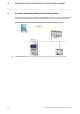
4 Creating a backup & carrying out recovery 4.1 Creating a backup ________________________________________________________________ 4.1.1 Creating a backup: with the Engineering PC (recommended variant) [4-1] Illustration example: »Backup & Restore« under Windows XP (Engineering PC) How to carry out a backup: 1. Connect the USB stick to the Engineering PC. 2. Start »Backup & Restore« on the Engineering PC. 3. Select the USB stick. 4. Select the Backup tab. 5.
4 Creating a backup & carrying out recovery 4.1 Creating a backup ________________________________________________________________ 4.1.2 Creating a backup: Directly on the controller [4-2] Note! Cabinet controllers with a DVI interface require an external Monitor Panel. Illustration example: »Backup & Restore« under Windows CE () How to carry out a backup: 1. Connect the USB stick to the USB interface of the controller. 2. Start »Backup & Restore« on the controller. 3. Select the Backup tab.
4 Creating a backup & carrying out recovery 4.1 Creating a backup ________________________________________________________________ 4.1.3 Alternative: Creating a backup with the »WebConfig« Tip! For Cabinet controllers, use the »WebConfig« without an external panel. Note! When operating the »WebConfig« it must be observed that the values from the controller are reimported if the Update button is clicked.
4 Creating a backup & carrying out recovery 4.1 Creating a backup ________________________________________________________________ How to carry out a backup using the »WebConfig«: 1. Connect a USB stick to the controller. 2. Start the »WebConfig«. 3. Navigate to the Backup Restore menu button. 4. Select the Backup menu item. 5. Select the Backup main action in the display area. 6. Assign the desired backup name in the input field. Further information: Components of the backup designation ( 22) 7.
4 Creating a backup & carrying out recovery 4.1 Creating a backup ________________________________________________________________ 4.1.4 Alternative: Windows Explorer - on "Directory/file" level Note! For carrying out a backup with the Windows Explorer only USB sticks which have previously been used for a »Backup & Restore« can be used.
4 Creating a backup & carrying out recovery 4.2 Carrying out restore and auto-restore ________________________________________________________________ 4.2 Carrying out restore and auto-restore 4.2.1 Note! • Before a restore is performed, a safety backup is created. • Remove (after carrying out the restore) the USB stick from the controller. • Only applies to Windows embedded Standard: After a restore has been performed, the file system is automatically checked (chkdsk.exe).
4 Creating a backup & carrying out recovery 4.2 Carrying out restore and auto-restore ________________________________________________________________ 10. Restart controller (with connected USB stick) by mains switching. • Contollers in Windows CE systems are automatically restarted. • The backup selected is restored. 11. After the boot-up of the controller: Remove the USB stick from the controller. 4.2.
4 Creating a backup & carrying out recovery 4.2 Carrying out restore and auto-restore ________________________________________________________________ 4.2.3 Alternative: »WebConfig« Tip! Use the »WebConfig« if the controller does not have a DVI interface or if no Monitor Panel is connected. How to carry out a restore: 1. Connect the USB stick to the controller. 2. Start the »WebConfig«. 3. Navigate to the Backup Restore menu button. 4. Select the Restore Update menu item 5.
4 Creating a backup & carrying out recovery 4.2 Carrying out restore and auto-restore ________________________________________________________________ 10. After the boot-up of the controller: Remove the USB stick from the controller. 4.2.4 Alternative: Windows Explorer - on "Directory/file" level In case the controller does not start anymore it is possible to manually prepare a USB stick at the Engineering PC, so that afterwards a restore can be carried out with it on the desired controller.
4 Creating a backup & carrying out recovery 4.2 Carrying out restore and auto-restore ________________________________________________________________ 4.2.5 Carrying out an auto-restore Note! • When executing an Auto-restore, a restore is carried out directly - no backup of the system is created before. • An auto-restore is an optimised process for carrying out a series commissioning. An auto-restore serves to automatically save identical backup data to multiple controllers.
4 Creating a backup & carrying out recovery 4.3 Carrying out an update/auto-update (only available for control technology) ________________________________________________________________ 4.3 Carrying out an update/auto-update (only available for control technology) 4.3.1 Note! A (software) update provided by Lenze is to be copied into the directory \Backup to the USB stick.
5 Diagnostics 5.1 Status LEDs of the controllers ________________________________________________________________ 5 Diagnostics 5.1 Status LEDs of the controllers The controllers are equipped with LEDs that signal the current operating status. Depending on the controller used, the colouring of the LEDs may vary.
5 Diagnostics 5.1 Status LEDs of the controllers ________________________________________________________________ LED Colour 1 / Colour 2 Yellow green/ blue* Yellow Interval Meaning constant The supply voltage has fallen below the minimum value (voltage failure/"Powerfail") blinking (2.0 Hz) Status after switch-on/restart (in preparation for c300/p300 controllers.) blinking (0.5 Hz) "System clock is not synchronised" (missing time information).
5 Diagnostics 5.2 Text outputs (optional panel/screen required) ________________________________________________________________ 5.2 Text outputs (optional panel/screen required) During the actions are processed, the software outputs information in the form of text messages and progress bars (requires optional panel/screen). The backup and restore processes pass through several successive steps. A sequence step can only be executed if the previous step has been successful.
5 Diagnostics 5.2 Text outputs (optional panel/screen required) ________________________________________________________________ Message Message Information / remedy E0 Failed to initialize hardware modules It is tried to carry out a backup or restore on an unknown device. • Use the approved Lenze hardware for carrying out the »Backup & Restore« processes. E1 ERROR: No Backup and Restore device found! The USB stick inserted does not contain a valid data structure.
5 Diagnostics 5.2 Text outputs (optional panel/screen required) ________________________________________________________________ Message Message Information / remedy E14 ERROR: Storage capacity of the selected backup is too small. Invalid backup! The control file does not match the backup, or the backup was manipulated. • Only use backups that are consistent in themselves. E15 ERROR: The size of the target device is too small.
5 Diagnostics 5.2 Text outputs (optional panel/screen required) ________________________________________________________________ During an update the following error messages may occur: Message Message in the logbook Remedy E1 System version is identical to the selected update package. No action necessary. The software version of the controller is already up to date (version identical to that of the update).
5 Diagnostics 5.3 Event of an error: Controller c300/p300 does not start ________________________________________________________________ 5.3 Event of an error: Controller c300/p300 does not start If Controller c300 or p300 does not start, the Lenze standard settings can be activated with the Reset button. How to activate the Lenze standard settings: 1. Switch off voltage supply. 2. Activate Reset button. 3.
Index ________________________________________________________________ 6 Index A L Activating the Lenze standard settings (Reset button) 40 Activating the standard settings (Reset button) 40 Application notes 9 Layout of the safety instructions 9 LEDs of the controllers 34 Log file 38 B Backup/Restore error messages 36 C Carrying out a restore/auto-restore Backup & Restore software application 28, 29 WebConfig (alternatively) 30 Windows Explorer (alternatively) 31 Carrying out an auto-restore 32 Back
)(('%$&. 42 Your opinion is important to us These instructions were created to the best of our knowledge and belief to give you the best possible support for handling our product. Perhaps we have not succeeded in achieving this objective in every respect. If you have suggestions for improvement, please e-mail us to: feedback-docu@lenze.com Thank you very much for your support.
Backup & Restore · Software Manual · SHPSTV3BCKNRST · 13450101 · DMS 1.3 EN · 04/2014 · TD17 Lenze Automation GmbH Postfach 10 13 52, D-31763 Hameln Hans-Lenze-Straße 1, D-31855 Aerzen Germany +49 5154 82-0 +49 5154 82-2800 lenze@lenze.com www.lenze.com Service Lenze Service GmbH Breslauer Straße 3, D-32699 Extertal Germany 008000 24 46877 (24 h helpline) +49 5154 82-1112 service@lenze.