INSTALLATION AND OPERATION MANUAL Free-Standing Pellet Stove Save These Instructions For Future Reference P/N 775228M, Rev. D, 01/2011 Pellet Stoves Model Winslow™ (PS40) A French manual is available upon request. Order P/N 775228CF. Portland Ce manuel d’installation est disponible en francais, simplement en faire la demande. Numéro de la pièce 775228CF. US Report No. 050-S-13-2 This appliance must be properly installed and operated in order to prevent the possibility of a house fire.
IMPORTANT SAFETY AND WARNING INFORMATION read THIS MANUAL IN ITS ENTIRETY and understand these Rules to follow for safety. WARNING Improper installation, adjustment, alteration, service or maintenance can cause injury or property damage. Refer to this manual. For assistance or additional information consult a qualified installer, service agency or the gas supplier. WARNING Do not attempt to alter or modify the construction of the appliance or its components.
Congratulations! When you purchased your new pellet stove, you joined the ranks of thousands of individuals whose answer to their home heating needs reflects their concern for aesthetics, efficiency and our environment. We extend our continued support to help you achieve the maximum benefit and enjoyment available from your new pellet stove. It is our goal at Lennox Hearth Products to provide you, our valued customer, with an appliance that will ensure you years of trouble-free warmth and pleasure.
Planning Your Installation Questions To Ask Local Building Official A correct installation is critical and imperative for reducing fire hazards and perilous conditions that can arise when wood pellet burning appliances are improperly installed. The installer must follow all of the manufacturers’ instructions. WARNING Check all local building and safety codes before installation. The installation instructions and appropriate code requirements must be followed exactly and without compromise.
Features and Specifications Installation Options • • • • • Residential and Commercial Vented vertical and horizontal (see venting instructions) Manufactured home and mobile home Thermostat or manual operation Bedrooms Heating • Max. feed rate is 4.7 pounds/hour or 39,500 BTU/hour • Min. feed rate is 1.8 pounds/hour or 15,120 BTU/hour Venting This stove is approved for venting with Type L and Type PL pellet vent pipe listed to UL 641 and ULC S609.
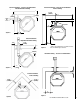
WARNING 4-1/8” (105mm) Do not burn treated seed corn! Seed corn is treated with chemical pesticides that are harmful or fatal if swallowed.
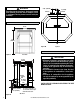
Corner Installations - Clearance to Combustibles Left Wall Horizontal Venting Parallel Installations - Clearance to Combustibles Vertical Venting 17-1/4” (423mm) 3” (76mm) 8” (203mm) 3" (76mm)* 6” (152mm) Top Vent 3” (76mm) Figure 3 Corner Installations Right Wall Horizontal Venting 8” (203mm) 6-3/4” (172mm) * Refer to pipe Manufacturer's installation instructions for minimum pipe clearances.
Minimum Size Hearth Protection Alcove Installations Minimum alcove height is 41” (1041 mm), minimum width is 42-1/4” (1073 mm) and maximum depth is 48” (1219 mm). Note, it is quite difficult to load pellets into the hopper when installed in an alcove only 41” (1041 mm) high. For alcove wall clearances see parallel clearances below.
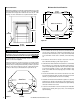
Vent TERMINATION LOCATIONS Air Supply Inlet Vent Terminal Area Where Terminal Is Not Permitted Vertical Terminal USA - 24” 1' Min. CANADA - 3' Min. (610mm) Vertical Terminal G (From Eave) USA - 1' Min. 24” CANADA(610mm) - 3' Min. A D E M Fixed Closed B H B C N L B K F J A B A= B= C= D= E= F= G= H= J= K= Refer to vent manufacturer's installation instructions for the required clearance above grade, veranda, porch, deck, or balcony. Clearance to window or door that may be opened (min.
INSTALLATION Horizontal Venting This stove is approved for venting with Type L and Type PL pellet vent pipe listed to UL 641 and ULC S609. We recommend the use of venting products manufactured by Security™ Chimneys International. Single wall pipe cannot be used with this pellet stove. The stove’s flue collar is 3” in diameter. An approved wall thimble or approved ceiling firestop must be used when the pellet pipe passes through a combustible wall or ceiling.
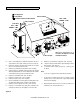
Masonry Chimney Fireplace When venting into a masonry chimney, the pellet pipe can terminate just inside the chimney. However, it is recommended to run the pellet pipe to the top of the chimney. When venting into a fireplace chimney, the pellet pipe can terminate just above the damper. However, it is recommended to run the pellet pipe to the top of the chimney. Optional Clean-Out Access Door Figure 16 Figure 18 Figure 17 Figure 19 NOTE: DIAGRAMS & ILLUSTRATIONS ARE NOT TO SCALE.
Vertical If the length of pipe exceeds 15 feet, 4 inch pipe rather than 3 inch vent pipe should be used. Rain Cap Storm Collar WARNING: DO NOT INSTALL THIS STOVE IN A SLEEPING ROOM IN A MANUFACTURED HOME. CAUTION: THE STRUCTURAL INTEGRITY OF THE MANUFACTURED HOME FLOOR, WALL AND CEILING/ROOF MUST BE MAINTAINED. Outside Air Installations Roof Flashing Connecting the Winslow PS40 stove to outside combustion air is required in manufactured home installations and when required by local building codes.
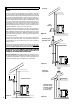
Door Trim Installation Instructions (A) (ref. form # 775274M) Trim Pieces Parts List (A): Qty (2) Trim Pieces (Gold, Nickel, Brushed Nickel or Black Nickel ) (6) #10 nuts (6) #10 washers Trim Screws #10 washers Tools Needed: Qty (1) 3/8” nut driver or socket wrench Figure 23 CAUTION: Always ensure that plated surfaces are clean and free of fingerprints before lighting stove. Fingerprints will leave permanent blemishes if left on plated surface when lit.
4. Place one washer on each stud. Using a 3/8” nut driver, snug up the nuts on each piece of trim. Do not finish tightening the nuts yet. See Figure 27. 5. There should be approximately a 7/8” (22 mm) gap between the top edge of the upper trim and the top edge of the door and a 1-1/2” (38 mm) gap between the bottom trim to the bottom of the door. Visually inspect the alignment of the trim and adjust if necessary. See Figure 28. 6. Finish tightening nuts.
Door Grill Installation Instructions 3. Rotate the grill back to the horizontal position and re-install the four button head screws through the two holes at each end of the grill and into the stove body. See Figure 31. (ref. form # 775273M) Parts Needed: Qty (4) Button Head Screws (already in place in stove) Tools Required: Qty (1) 1/8” allen wrench Rotate Grill Back To Horizontal Position To install the Grill: 1. Remove the four button head screws from body of the stove with a 1/8” allen wrench.
2. Remove all pellets and ash from the firebox to ensure a proper fit for the brick panel. Brick Panel Installation Option: Part #79030 3. Insert the brick panel, top first, as shown in Figure 35. The two cut out corners should be at the bottom. Kit Contents: - Brick Panel (A) - 4 Tap Tights (B) Tools Required: - Drill (90° drill recommended) - #18 drill bit - 5/32 allen wrench A Figure 33 Figure 35 B Note: The brick panel comes pre-painted with Metallic Black paint.
5. Screw in the four tap tights, included with this kit, using a 5/32 allen wrench. 6. Replace the Burn-Pot and check that it is firmly in place (if you can rotate the Burn-Pot it is not installed correctly). If present, install the optional log set according to the log set installation instructions (included with your log set). 7. Re-hang the door by reversing the instructions in step 1. Figure 37 NOTE: DIAGRAMS & ILLUSTRATIONS ARE NOT TO SCALE.
Log Set Installation Instructions (ref. form # 775275M) Kit Contents (refer to Figure 38) 1 ea. 1 ea. 1 ea. 2 ea. 1 ea. Left Log (A) Right Log (B) Front Log (C) Log Support Brackets (D) Instruction Sheet D bend lines Cat. No.
Lighting Operation Control Board The control board regulates all functions of the stove. The following is a list of the board’s components: • Feeding light - lights up when the auger is feeding pellets into the Burn-Pot. • Ready Light - lights up when stove is ready to operate. Igniting Light - lights up when the stove is in the ignition sequence. • Start Button - is pushed to start the ignition sequence after the heat selector knob is turned from off.
Shut Down Normal - To turn the stove off, turn the heat selector knob to off. The fans will continue to operate until the control board completes the shut down cycle. Once you find a pellet brand that burns well, continue using this brand. High ash fuel increases the frequency of stove cleaning. Fuel with an excessive moisture content may jam the auger assembly. Corn Fuel Power Outage - If the stove loses electrical power for less than 10 seconds it will continue to operate.
Cleaning Glass Cleaning and Maintenance IMPORTANT CAUTIONS: • UNPLUG POWER CORD AND ENSURE APPLIANCE IS COLD BEFORE PERFORMING ANY MAINTENANCE WORK. • Some brands of pellets produce more ash and clinkers than others. Therefore the frequency of performing the following cleaning procedures depends to a great degree on the quality of the pellets burned. • Not cleaning this unit will cause it to burn poorly and will void your warranty for this appliance.
Inspect Gaskets Inspect the condition of the rope gasket around the door, window and ash drawer, periodically, and replace if necessary. Inspect the die-cut gaskets on the access covers (B and C in Figure 45A) and replace if necessary. Cleaning the Heat Exchanger (Recommended Frequency of 2 days to 2 weeks*) CAUTION: Do not operate the heat exchange scraper when the stove is hot.
Cleaning the Vent Pipe (Recommended Frequency of Yearly*) Soot and Fly-Ash: Formation and Need for Removal - The products of combustion will contain small particles of fly-ash. The fly-ash will collect in the exhaust venting system and restrict the flow of the flue gases. Incomplete combustion, such as occurs during start-up, shutdown, or incorrect operation of the room heater will lead to some soot formation which will collect in the exhaust venting system.
Proof of Fire Switch (Recommended Frequency of 1 year or after every 100 bags of fuel used*) This switch needs to be removed and cleaned after every 100 bags of fuel burned. Cleaning Procedure: 1. UNPLUG STOVE! 2. Locate the switch on the combustion blower (see Figure 52). 3. Using a flat-head screwdriver, remove the 2 screws which secures the switch to the blower housing. 4. Using a dry cloth, wipe off any flyash build-up on the sensor portion of the switch. 5. Reinstall switch.
Component Information Flue Outlet The following is a list of components and their functions. Igniter The Winslow™ PS40 stove comes equipped with an automatic igniter for lighting the fuel when the stove is in the lighting mode. The igniter superheats air that is pulled through the Burn-Pot by the combustion blower to light the fuel. The igniter remains energized for the first seven minutes of the lighting sequence.
Draft Adjuster - Adjustment Procedure After the draft adjuster is adjusted, re-evaluate the appearance of the flame. It may be necessary to continue adjusting it in increments until proper combustion is achieved (the flame should become a brighter yellow and begin to “dance”). The Winslow™ PS40 stove has a draft adjuster located at the left side of the stove directly in front of the combustion blower.
Diagnostic Codes If the stove operates abnormally, the ready light on the control board will signal the nature of the abnormal operation.
Over Temperature Snap Switch Shuts Stove Down - Code - Ready light flashes red 2 long blinks Possible Problem Solution Convection blower not running Blower dirty, blower snap switch bad, or blower broken Flue passageways or vent restricted Clean passageways or vent pipe (see Pages 22 and 23) Snap switch* defective Replace the snap switch* * Note: The snap switch has a reset button that must be pushed before stove will function (see Page 25).
REPLACEMENT PARTS - WINSLOW™ PS40 Cat. No.
Accessories Door Trim (required - sold separately) (ref. Form # 775274M) Item No. Cat. No. Model Description 1 79038 P40DT-B Black 2 79034 P40DT-G Gold 3 79037 P40DT-N Nickel 4 79035 P40DT-BRN Brushed Nickel 5 79036 P40DT-BLN Black Nickel Door Trim (1-5) Grill Kits (required - sold separately) (ref.
Accessories 11 Common Accessories Item No. Cat. No. Model Description 11 H5142 P40LOG 12 79030 P40BRICK Log Set (ref. Form # 775275M) 13 H4635 DWTK Digital Wall Thermostat Kit 14 70005 RT-AC Remote Control w/Thermostat, Alternating Current (ref. Form # 775280M) 15 H0251 RCL-STAT Deluxe Remote Control (Timer, T-Stat, Clock) (ref. Form # 750129M) 16 H6907 P40DIAG Diagnostic Tool (ref.
Warranty Your pellet stove is covered by a limited warranty (provided with appliance). Please read the warranty to be familiar with its coverage. Retain this manual. File it with your other documents for future reference. Product reference information We recommend that you record the following important information about your fireplace. Please contact your Lennox Hearth Products dealer for any questions or concerns. For the number of your nearest Lennox Hearth Products dealer, please call 1-800-9-LENNOX.