APPLICATION GUIDE WING
Congratulations you have made a wise choice with the purchase of your Lennox air conditioning unit. This product has been designed, assembled and supplied in one of our world class manufacturing facilities and we feel sure that it will meet your expectations. Lennox an international organisation with world wide distribution takes pride in supplying you with this product. CONTENTS CONTENTS PÁGE . PRODUCT RANGE . SYSTEM CONFIGURATION . GENERAL DESCRIPTION . SPECIFICATIONS . ELECTRICAL DATA .
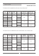
PRODUCT RANGE COOLING ONLY R-407C LTX INDOOR UNIT IN COMBINATION, WITH AXIAL FAN OUTDOOR UNIT MODEL OUTDOOR UNIT INDOOR UNIT V / Ph / 50 Hz NOMINAL CAPACITY W COOLING ONLY NOMINAL CAPACITY KW COOLING ONLY WING 2,8TFK KJF 2,8K LTX 3 230V-1Ph 7.350 3,06 WING 3TFK KJF 3K WING 3TFK KJF 3K 9.500 3,85 WING 3TFK KJF 3K 400 V - 3Ph WING 4TFK KJF 4K 230 V - 3Ph WING 4TFK KJF 4K 11.600 4,70 WING 5TFK KJF 5K WING 5TFK KJF 5K 13.
PRODUCT RANGE HEAT PUMP HEAT PUMP R-22C LTX INDOOR UNIT IN COMBINATION, WITH AXIAL FAN OUTDOOR UNIT MODEL OUTDOOR UNIT INDOOR UNIT V / Ph / 50 Hz WING 2,8TB KJB 2,8 LTX 3 230V-1Ph WING 3TB KJB 3 WING 3TB KJB 3 WING 3TB KJB 3 WING 4TB KJB 4 NOMINAL CAPACITY W NOMINAL CAPACITY KW COOLING ONLY HEAT PUMP COOLING ONLY HEAT PUMP 7.350 7.800 3,06 2,60 9.250 9.000 3,70 3,00 11.600 12.100 4,70 3,90 13.700 14.
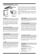
SYSTEM CONFIGURATION (INDOOR UNIT) IMPORTANT Prior of making the electrical connections, set the switch for heat pump unit or for cooling only unit. This unit is valid for operating as a cold only or heat pump application. The unit should be configured prior to making the electrical connections, by setting the configuration switch as follows: SWITCH MODEL Switch 2 Switch 1 ON 1 2 COOLING ONLY (*) OFF ON HEAT PUMP ON ON (*) Configuration from factory..
GENERAL DESCRIPTION INDOOR UNIT LTX OUTDOOR UNIT KJF/KJB The ceiling air conditioner SPLIT, on version cooling only and heat pump, are units air condensed. The indoor unit with direct air supply, realise function of cooling , heating dehumidification, cleaning air of the sites. Also the option to incorporate with maximum facilities a heating resistance on units cooling only and also on heat pump units.
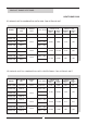
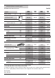
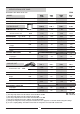
SPECIFICATIONS COOLING ONLY R-407C OUTDOOR UNIT WITH AXIAL FAN MODEL Cooling capacity (*) W OUTDOOR UNIT COMPRESSOR Nª / Type WING 2,8TFK WING 3TFK WING 4TFK WING 5TFK 7.350 9.500 11.600 13.500 KJF 2,8K KJF 3K KJF 4K KJF 5K 1 / ALT. 1 / ALT. 1 / ALT. 1 / ALT. 3.100 5.100 5.400 5.400 1650 2500 2600 2600 Capillary Capillary Capillary FAN Air flow outdoor unit REFRIGERANT m3/h. Type / R-407C gr. EXPANSIÓN (1) Capillary WEIGHT Kg 78 85 96 98 DIMENSIONS Height mm.
SPECIFICATIONS COOLING ONLY R-407C OUTDOOR UNIT WITH CENTRIFUGAL FAN MODEL W (*) Cooling capacity OUTDOOR UNIT COMPRESSOR Nª / Type WING 2,8CFK WING 3CFK WING 4CFK WING 5CFK 7.180 9.100 12.100 14.000 KCF 2,8K KCF 3K KCF 4K KCF 5K 1 / ALT. 1 / ALT. 1 / ALT. 1 / ALT. 2.500 2.500 3.400 5.000 40 40 50 50 2255 2350 3070 4950 FAN Air flow outdoor unit m3/h. Available pressure Pa REFRIGERANT Type / R-407C gr.
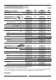
SPECIFICATIONS HEAT PUMP R-22 OUTDOOR UNIT WITH AXIAL FAN MODEL WING 2,8TB WING 3TB WING 4TB WING 5TB Cooling capacity (*) W 7.350 9.250 11.600 13.700 Heating capacity (**) W 7.800 9.000 12.100 14.600 KJB 2,8 KJB 3 KJB 4 KJB 5 1 / ALT. 1 / ALT. 1 / ALT. 1 / ALT. m3/h. 3.100 3.100 5.400 5.600 gr.
SPECIFICATIONS HEAT PUMP R-22 OUTDOOR UNIT WITH CENTRIFUGAL FAN MODEL WING 2,8CB WING 3CB WING 4CB WING 5CB Cooling capacity (*) W 7.180 9.100 12.100 14.000 Heating capacity (**) W 8.150 10.220 13.500 17.400 KCB 2,8S KCB 3S KCB 4S KCB 5S 1 / ALT. 1 / ALT. 1 / ALT. 1 / ALT. 2.500 2.500 3.400 5.000 40 40 50 50 OUTDOOR UNIT COMPRESSOR Nª / Type FAN Air flow outdoor unit m3/h. Available pressure Pa REFRIGERANT Type / R-22 gr.
SPECIFICATIONS SET WITH AXIAL FAN OUTDOOR UNIT SOUND LEVEL Sound pressure (Lp) level Indoor unit (1) dBA Outdoor unit (2) dBA WING 2,8TFK WING 2TB WING 3TFK WING 3TB 41/46 (*) 41/46 (*) 41/46 (*) 43/48 (*) 43/48 (*) 55 53 56 56 52 WING 4TFK WING 4TB WING 5TFK WING 5TB (1) Sound level measured to a distance of 2m from the unit, normal absorption, room size according to unit capacity. (2) Sound level measured to a distance of 5 m, free space.
SPECIFICATIONS SET WITH CENTRIFUGAL FAN OUTDOOR UNIT WING 2,8CFK WING 2CB SOUND LEVEL Sound pressure (Lp) level WING 3CFK WING 3CB WING 4CFK WING 4CB WING 5CFK WING 5CB Indoor unit (1) dBA 41/46 (*) 41/46 (*) 43/48 (*) 43/48 (*) Outdoor unit (2) dBA 57 58 60 62 (1) Sound level measured to a distance of 2m from the unit, normal absorption, duct size and installation according to unit capacity.
ELECTRICAL CONNECTIONS MODELS 2,8-3-4-5 1 OUTDOOR UNIT 2 3 ELECTRIC WIRING DIAGRAM For electrical connection refer to wiring diagram in the unit 1 Power supply 2 Connection indoor unit with outdoor unit 3 Sensor connection 1º Remove the front details at the corners and unit cover panel.
ELECTRICAL CONNECTIONS AND SYSTEM CONFIGURATION IMPORTANT Prior of making the electrical connections, set the switch for heat pump unit or for cooling only unit. This unit is valid for operating as a cold only or heat pump application. The unit should be configured prior to making the electrical connections, by setting the configuration switch as follows: 1 3 Remove the front details at the corners and unit cover panel. Rolling side DETALLE A 2 Remove the filters (1) Filters Sides and carcass P.C.
ELECTRICAL CONNECTIONS COOLING ONLY PE L N 1 2 3 PE L N 1 2 LTX 3 3 4 OUTDOOR UNIT 5 230V/50HZ 1Ph + N PE L N 1 2 3 PE L1 L2 L3 L3 N LTX 3-5 N 1 2 PE L 5 4 3 N 1 PE L1 L2 L3 L3 N OUTDOOR UNIT LTX 3-5 2 3 N 1 2 OUTDOOR UNIT 5 4 3 230V/50HZ 3Ph 400V/50HZ 3Ph + N Wire overwhelm HEAT PUMP CONTROL SENSOR 4 5 PE L N 1 2 3 4 5 PE L N N 1 2 LTX 3 3 OUTDOOR UNIT 230V/50HZ 1Ph + N CONTROL SENSOR CONTROL SENSOR 4 5 PE L 4 5 PE L1 L2 L3 N N 1 2 3 N 1
OUTDOOR UNIT MOTOR-FAN CHARACTERISTICS OUTDOOR UNIT WITH CENTRIFUGAL FAN AIR FLOW AIR FLOW m 3/h m 3/h KCF2,8K / KCB 2,8S KCF 3K / KCB 3S STATIC PRESSUERE AVIALABLE Pa. STATIC PRESSUERE AVIALABLE Pa. 110 75 40 0 100 70 54 0 1500 1700 2500 2900 1500 1650 2500 2900 KCF 4K / KCB 4S KCF 5K / KCB 5S STATIC PRESSUERE AVIALABLE Pa. STATIC PRESSUERE AVIALABLE Pa.
OPERATING LIMITS OPERATING LIMITS COOLING ONLY UNITS 46° DB * Supply air temperature into the outdoor unit ºC ** Supply air temperature into the indoor unit ºC STANDARD * L.A.C. ON/OFF L.A.C. PROPROC 19° DB -10° DB 21°/15º DB/WB DB.- Dry Bulb WB.
REFRIGERANT CONNECTIONS Flared nuts INDOOR UNIT Coupling Service valve OUTDOOR UNIT Protective hoods Insulation REFRIGERANT CONECTION FOR UNITS WITH COUPLINGS AND SERVICE VALVES NOTE: THE REFRIGERANT LINES GAS AND LIQUID, MUST BE INSULATED Make the refrigerant connections between the outdoor and indoor unit, as follows: -With the valves closed on outdoor unit, unscrew the flare nuts, removing all the protective hoods.
REFRIGERANT CONNECTIONS DISTANCES BETWEEN UNITS To locate the outdoor and the indoor units, refer to the following information. L : Distance length between both units. 1 = Refrigerant vapour line. 2 = Liquid aspiration line. INDOOR U. OUTDOOR U. 2 L OUTDOOR U. 2 1 1 L INDOOR UNIT OUTDOOR U. 1 INDOOR U. 2 L 2,8 3 4 Liquid 3/8" 3/8" 3/8"(1) 1/2" Vapour 5/8"(1) 3/4" 3/4" 3/4" Máx.
REFRIGERANT CONNECTIONS REFRIGERANT CHARGE OUTDOOR UNITS TYPE KJF-K/ KJB 2,8 3 4 5 (gr.) (*) (gr.) (**) 1.650 2.500 2.600 2.600 5 5 5 5 (gr.) (***) 30 30 30 55 (gr.) (*) 1.775 2.500 2.800 3.500 (gr.) (**) 5 5 5 5 (gr.) (***) 45 45 45 105 MODEL COOLING ONLY HEAT PUMP OUTDOOR UNITS TIPO KCF-K/ KCB 2,8 3 4 5 (gr.) (*) (gr.) (**) 2.255 2.350 3.070 4.950 5 0 5 5 (gr.) (***) 30 30 30 55 (gr.) (*) 2.425 2.525 3.400 5.300 (gr.) (**) 5 0/5 5 5/0 (gr.
DIMENSIONS OF OUTDOOR UNIT WITH CENTRIFUGAL FAN (mm.) MODELS KCF-K / KCB-S 2,8-3 MAXIMUM DIMENSIONS A A C B B C MODELS KCF-K / KCB-S- 4-5 A C B AIR OUT STANDARD SETTING UP TEMPLATE (mm) UNITS 2-2,5-2,8-3 KCF-K KCB-S 2,8-3 4 5 A 490 525 575 B 1050 1300 1300 C 750 830 830 A 505 525 575 B 1100 1300 1300 C 841 890 890 AIR IN STANDARD A AIR IN OPTIONAL B B AIR OUT OPTIONAL Use 4 rod of a diameter of 10mm if the unit is fixed in the roof , or screw M.
DESCRIPTION OUTDOOR UNIT KCF-K / KCB 2,8-3 14 15 13 1 14 AIR IN STANDARD 15 2 10 33 6 4 5 7 8 12 1 FAN 10 DRAINGE ( O 16 EXTERNAL) 2 EXCHANGER 11 REARM ON ON HIGH PRESSOSTAT 3 COMPRESSOR 12 INTAKE PRESSURE (MOD.
DESCRIPTION OUTDOOR UNIT KCF / KCB-S 4 - 5 1 8 9 2 6 4 3 7 3 5 6 1 FAN 2 EXCHANGER 3 COMPRESSOR 8 11 12 AIR OUT POSICIÓN STANDARD POSICIÓN OPCIONAL 4 ELECTRICAL BOX 5 CONNETION PIPE 6 ACCESS PANEL TO COMPRESSOR AND PIPES COMPONENTS 7 9 10 8 9 AIR IN POSITION STANDARD POSTION OPTIONAL ACCESS PANEL TO ELECTRICAL BOX 10 DRAINGE ( O 16 EXTERNAL) 11 ELECTRICAL SUPPLY ENTRY ELECTRICAL SUPPLY 12 MAIN SWITCH (OPTIONAL) 5 8 9 6 12 10 11 22
ENTRANCE STANDARD/ OPTIONAL OUTDOOR UNIT KCF-K / KCB ENTRANCE STANDARD MODELS 2,8-3 E E E RETURN AIR OPTIONAL SUPPLY AIR D F F RETURN AIR A G B H K 25 C RETURN AIR STANDARD E E ENTRANCE OPTIONAL (TO BE REALISE BY THE INSTALLATOR F D A B J K F D SUPPLY AIR OPTIONAL SUPPLY AIR RETURN AIR M SUPPLY AIR STANDARD L L RETURN AIR OPTIONAL MODELS 4-5 E K ENTRANCE STANDARD F D N SUPPLY AIR RETURN AIR A G B RETURN AIR STANDARD H C M A B N SUPPLY AIR J K F RETU
DIMENSIONS AND SETTIING UP TEMPLATES OF OUTDOOR UNIT WITH AXIAL FAN FLOOR MOUNTED Mi n . 15 0 (* *) KJF-K KJB Ø 12 KJF-K KJB E F Min. 300 (**) G Min. 300 (**) D E F B OUTDOOR UNIT KJF-2.8K KJF-3K C KJB-2.8 A (**) A B C D E F G ALWAYS KEEP FREE KJF-4K KJB-3 KJB-4 973 781 333 620 176,4 973 1.035 973 781 973 1.035 333 620 176,4 333 620 176,4 333 620 176,4 10 343,5 10 343,5 10 343,5 10 343,5 KJF-5K KJB-5 973 1.035 333 620 176,4 10 343,5 1.005 1.
INSTALLATION INDOOR UNIT INSTALLATION UNIT Install the unit in a way that the discharge air would not be direct to persons, differences of temperature can create disturbs. Keep in mind in the installation of the unit, some ambient can supply electromagnetic radiation that can affect the good function of the unit, follow then the following instruction recommended in this document. Rolling sides A A To remove the casing, slide them over the rolling sides and remove horizontally (See picture A).
INDOOR UNIT OPTIONALS ELECTRICAL HEATER BEFORE ATTEMPTING TO PERFORM ANY SERVICE OR MAINTENANCE, TURN OFF THE ELECTRICAL POWER, AND CHECK THAT THE FAN HAS STOPPED 1 2 3 4 5 To remove the casing, slide them over the rolling sides and remove horizontally Remove the filters. Remove drain pan. Introduce the electrical heater kit rods in the holes of one side of the coil and fix with screws on the other. Fix the contactor to the fan deck.
OUTDOOR UNIT OPTIONALS MAIN SWITCH The main swicth is located on the access panel to the electrical box, in such a way that the unit is disconnected when the panel is opened, for the models KCF and KCB. (Refer to the size diagram on pages 25 to 30, to see the position of the electrical box access panel) WINTER CONTROL The low ambient kit should be fitted to the cooling units, when the outdoor temperature is lower then 19 ºC. in cooling cycle.Keeps condensing temperature constant aprosimatelly 40ºC.
MAINTENANCE OF THE UNIT POSSIBLE PROBLEMS PROBLEM 1.- Unit do not work. 2.- The fan of the unit works quicker without any SOLUTION • Check electrical supply of the unit. • Check electrical connexion. • Check the remote controller and parameter works correctly. • Check that the filter of the unit is clean. • Check electrical connexion. • If the problem persist, check the function of the motor. 3.- Noise on pipe system. NOTE: Some noises are • Check refrigerant charge is correct.
POINTS TO KEEP IN MIND Abrasive surfaces Low temperatures High temperatures Risk of injury with moving objects WARNING Electric shock hazard can cause injury or death. Before attempting to perform any service or maintenance on the unit, turn OFF the electrical power, and check that the fan has stopped.
30
BELGIUM : CZECH REPUBLIC : FRANCE : GERMANY : LENNOX BENELUX N.V./S.A. tél. : + 32 3 633 30 45 fax : + 32 3 633 00 89 e-mail : info.be@lennoxbenelux.com LENNOX JANKA tél. : + 420 2 510 88 111 fax : + 420 2 579 10 393 e-mail : janka@janka.cz LENNOX FRANCE tél. : + 33 4 72 23 20 20 fax : + 33 4 78 20 07 76 e-mail : accueil@lennoxfrance.com LENNOX DEUTSCHLAND GmbH tél. : + 49 69 42 09 79 0 fax : + 49 69 42 09 79 40 e-mail : info.de@lennoxdeutschland.com MIDDLE EAST : LENNOX DISTRIBUTION tél.