INSTALLATION AND OPERATION MANUAL EPA CERTIFIED CATALYTIC FREESTANDING WOODSTOVE RETAIN THESE INSTRUCTIONS FOR FUTURE REFERENCE Ce manuel d'installation est disponible en francais, simplement en faire la demande. MODEL T150C THIS APPLIANCE MUST BE INSTALLED BY A QUALIFIED TECHNICIAN. READ MANUAL THOROUGHLY BEFORE INSTALLATION. P/N 775008M, Rev.
IMPORTANT WARNINGS CAUTION: PLEASE READ THIS ENTIRE MANUAL BEFORE YOU INSTALL AND USE YOUR NEW ROOM HEATER. FOR YOUR SAFETY, FOLLOW THE INSTALLATION, OPERATION AND MAINTENANCE INSTRUCTIONS EXACTLY, WITHOUT DEVIATION. FAILURE TO FOLLOW THESE INSTRUCTIONS MAY RESULT IN PROPERTY DAMAGE, BODILY INJURY, OR EVEN DEATH. IF THIS APPLIANCE IS NOT PROPERLY INSTALLED, A HOUSE FIRE MAY RESULT. CONTACT YOUR LOCAL BUILDING OR FIRE OFFICIALS ABOUT RESTRICTIONS AND INSTALLATION INSPECTION REQUIREMENTS IN YOUR AREA. 1. 2.
TABLE OF CONTENTS CONGRATULATIONS ON THE PURCHASE OF YOUR NEW WOODSTOVE MANUFACTURED BY LENNOX HEARTH PRODUCTS. Important Warnings ................................................ 2 Testing/Listing, EPA, Using this Manual ................. 3 When you purchased your new woodstove, you joined the ranks of thousands of concerned individuals whose answer to their home heating needs reflects their concern for aesthetics, efficiency and our environment.
PLANNING YOUR INSTALLATION QUESTIONS TO ASK LOCAL BUILDING OFFICIAL A correct installation is critical and imperative for reducing fire hazards and perilous conditions that can arise when wood burning appliances are improperly installed. The installer must follow all of the manufacturers’ instructions. The installation of a wood burning appliance must conform to local codes and applicable state and federal requirements. Familiarity with these requirements before installation is essential.
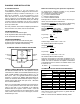
PLANNING YOUR INSTALLATION FLOOR PROTECTION This appliance requires ½" (13 mm) minimum noncombustible floor protection designed for solid fuel burning appliances having a thermal conductivity of k = .84 BTU in/ft or equivalent. If the floor protection is to be stone, tile, brick, etc., it must be mortared or grouted to form a continuous non-combustible surface (See Using Alternate Material As Floor Protector below).
PLANNING YOUR INSTALLATION SELECTING A LOCATION The design of your home and where you place your stove will determine its value as a source of heat. A woodstove depends primarily on air circulation (convection) to disperse its heat, and therefore, a central location is often best. There are other practical considerations, which must be considered before a final selection of locations is made. ♦ ♦ ♦ ♦ ♦ ♦ ♦ COMBUSTIBLE WALL CLEARANCE WARNING! IT IS VERY IMPORTANT THAT YOU OBSERVE THE MINIMUM CLEARANCES.
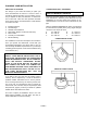
PLANNING YOUR INSTALLATION INSTALLATION REDUCED MASONRY STRUCTURE CLEARANCE (ALCOVE) Your stove can be installed in a masonry structure with reduced clearances if the structure was built to National Building Code for fireplaces and chimneys (UBC 37). INSTALLING (OPTIONAL) MARBLE ACCENTS See Optional Accessories, page 25 for ordering information.
INSTALLATION TYPES OF CHIMNEYS The chimney is a vital part of your stove installation. A properly built masonry chimney or a properly installed factory built chimney will assure a consistent draft under a variety of weather conditions (a smoking stove is usually caused by a chimney problem). The stove flue size is 6 inches (I52 mm) diameter, which is approximately 28 square inches (711 square mm) minimum.
INSTALLATION CHIMNEY HEIGHT REQUIREMENTS The chimney must extend 3 feet (914 mm) above the level of roof penetration and a minimum of 2 feet (610 mm) higher than any roof surface within 10 feet (305 cm) (see below). Check with your local building officials for any additional requirements for your area.
INSTALLATION RESIDENTIAL INSTALLATION DIAGRAM PAGE 10
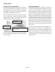
INSTALLATION Combustible Wall Chimney Connector Pass-Throughs A Method A. 12 inch (305 mm) Clearance to Combustible Wall Member: Using a minimum thickness 3.5 inch (90 mm) brick and a 5/8 inch (16 mm) minimum wall thickness clay liner, construct a wall pass-through. The clay liner must conform to ASTM C315 (Standard Specification for Clay Fire Linings) or its equivalent. Keep a minimum of 12 inches (305 mm) of brick masonry between the clay liner and wall combustibles.
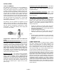
PRODUCT FEATURES AND CONTROLS PRIMARY AIR CONTROL The primary combustion air delivery is controlled by the Primary Air Control Assembly (The control knob is located above the fuel door). The heat output can be controlled by sliding the handle to a higher or lower heat output setting (See Care and Operation Section – Primary Air Control, page 13). The fuel, the amount of heat and burn times desired, the type of installation are all variables that will affect the control setting.
CARE AND OPERATION FUEL DOOR CAUTION: WHEN OPENING THE DOOR, DO NOT EXTEND IT BEYOND ITS NORMAL TRAVEL. OVEREXTENDING THE DOOR TO A FURTHER OPEN POSITION CAN PUT EXCESSIVE STRESS ON HINGE AREA OF DOOR AND HINGE PINS AND MAY RESULT IN BREAKAGE. PRIMARY AIR CONTROL This appliance is equipped with a control for the combustion air located above the fuel door. Slide the control to the right for a slower burn rate, to the left for a higher burn rate.
CARE AND OPERATION BREAK-IN PERIOD Your stove finish is a high temperature paint that requires time and temperature to completely cure. We recommend that you ventilate the house during the initial burns. The paint emits non-toxic odors during this process. KEEP YOUR HOUSE WELL VENTILATED DURING THE CURING PROCESS TO PREVENT ACTIVATION OF YOUR HOME SMOKE DETECTOR. HOW TO START AND MAINTAIN A FIRE 1. OPEN the bypass damper control by pulling it toward you.
CARE AND OPERATION Refueling * 1. Open the damper bypass control by pulling it toward you. 2. Set the primary air control set to high. 3. Open the door approximately 1/2 inch (13 mm), then wait for about thirty seconds. Open the door and add wood, then close the door. 4. If the optional temperature probe is used wait for a reading of approximately 600 degrees, then close the damper bypass control (push it in).
FUEL BURN RECOMMENDED FUEL This appliance is approved for use with untreated natural dry wood only (see Important Warnings, page 2, #8). Burning materials other than natural wood will shorten the life of the catalytic combustor. Do not burn particleboard or pressed logs using bonding agents as they can produce conditions that will deteriorate metal or damage the catalyst. Green or uncured wood does not work well as fuel, and can cause increased creosote buildups and plugging of the catalytic combustor.
MAINTENANCE SMALL AREA PAINT TOUCH-UP The stove body is painted with a quality hightemperature stove paint. Use only model TSPK-B Stove Paint, Catalog # 70K99. Do not touch-up your stove with any other paint. Using one small piece of 320 grit sand paper and lightly sand the blemish so that the edges are “feathered” or smooth to the touch between the painted and bare surfaces. Do not let the sand paper gum up with paint, as this will cause scratches on the metal surface.
MAINTENANCE CREOSOTE FORMATION AND NEED FOR REMOVAL What is Creosote - When wood is burned slowly, it produces tar and other organic vapors, which combine with expelled moisture to form creosote. The creosote vapors condense in the relatively cool chimney flue of a slow-burning fire. As a result, creosote residue accumulates on the flue lining. When ignited this creosote makes an extremely hot fire. Also, creosote deposits tend to form in long runs of venting where gases become too cool prior to exhausting.
MAINTENANCE CATALYTIC COMBUSTOR Your stove has been designed with a catalytic combustor, which will improve the overall efficiency of your stove. Removing the combustors for cleaning, inspection and reinstallation should be done at least once a year. Cleaning the combustors helps reduce buildup of ash and retarding chemicals. To clean the combustors, a soft brush, vacuum cleaner, or pipe cleaner may be used.
TROUBLESHOOTING SMOKES OUT FUEL DOOR WHEN OPEN (see ✸) 1. The primary air control is closed. 2. The chimney is too cool. Set the primary air control on "HIGH" with the bypass damper control "OPEN" for a few minutes before opening the fuel door. 3. Excess creosote will not only restrict your draft but it will create a risk of a creosote fire. Strictly adhere to maintenance requirements as outlined in this manual.
TROUBLESHOOTING CATALYST SUBSTRATE CRACKING 1. Normal operation, as long as combustor remains intact. If cracking causes large pieces to fall out, replace combustor. 2. Mishandling or abuse. Handle with care. 3. Warped housing (see Overfiring Damage on this page). CATALYST SUBSTRATE 1. Extreme thermal shock. Combustor is being worked too hard. 2. Excessive draft. Correct installation (see Draft Requirements, page 9).
SPECIFICATIONS: Model T150C Approximate Heat Capacity Up to ~1800 sq. ft. Up to ~550 sq. M Maximum Burn Rate 49,027 BTU EPA BTU Range 6500 / 35,300 BTU Emissions Rate (grams/hr.) 4.1 Efficiency Rating 72% Outside Air Provision No Maximum Log Length 22" (559 mm) Firebox Size (cubic feet) 2.5 c.f. (762 cu. mm) Stove Back to Flue Center 8" (203 mm) Flue Position Top Flue Collar Size 6" (152 mm) Approx Burn Time 8 - 12 hours Fuel Capacity 55 lbs.
REPLACEMENT PARTS FOR MODEL: T150C Part No.
COMPONENT DIAGRAMS: T150C FIREBRICK (1 ¼” thick) Part Qty FB-1 9 CATALYTIC COMBUSTOR System Components Dimensions 9 x 4 ¼” Regular Top View Showing Brick Installed PAGE 24
OPTIONAL ACCESSORIES: T150C Note: Install and use accessories per instructions provided with the accessory kit.
SAFETY/LISTING LABEL PAGE 26
EPA LABEL Page 27
OWNERSHIP RECORDS Dealer’s Name: Dealer’s Address: City: State: Zip Code: Serial Number: Date of Purchase: Date Installed: Notes: SERVICE AND MAINTENANCE LOG Service Service Service Date Technician Description Page 28
1110 West Taft Avenue Orange, CA 92865