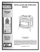
INSTALLATION AND OPERATION MANUAL FREESTANDING PELLET FIRED STOVES RETAIN THESE INSTRUCTIONS FOR FUTURE REFERENCE Freestanding Model T300P Series These appliances must be properly installed and operated in order to prevent the possibility of a house fire. Please read this entire owner's manual before installing and using your pellet stove. Failure to follow these instructions could result in property damage, bodily injury or even death.
IMPORTANT WARNINGS CAUTION: Read this manual thoroughly before starting installation. For your safety, follow the installation, operation and maintenance instructions exactly without deviation. Failure to follow these instructions may result in a possible fire hazard and will void the warranty. If this appliance is not properly installed, a house fire may result. Contact local building or fire officials about restrictions and installation inspection in your area. 1.
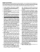
TABLE OF CONTENTS Important Warnings ................................................ 2 CONGRATULATIONS ON THE PURCHASE OF YOUR NEW PELLET STOVE MANUFACTURED BY LENNOX HEARTH PRODUCTS. Testing / Listing, EPA, Using this Manual................ 3 Planning Your Installation ..................................... 4-6 Manufactured (Mobile) Home Installation ................
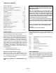
PLANNING YOUR INSTALLATION QUESTIONS TO ASK LOCAL BUILDING OFFICIAL A correct installation is critical and imperative for reducing fire hazards and perilous conditions that can arise when wood pellet burning appliances are improperly installed. The installer must follow all of the manufacturers’ instructions.
PLANNING YOUR INSTALLATION FLOOR PROTECTION This appliance requires noncombustible floor protection. If the floor protection is to be stone, tile, brick, etc., it must be mortared or grouted to form a continuous non-combustible surface. If a chimney connector extends horizontally over the floor, the protection must cover the floor under the connector and at least 2" to either side.
PLANNING YOUR INSTALLATION Clearances to combustibles are determined from testing to applicable standards for allowable heat transfer. The clearances allowed as shown here, do not take into account operation or serviceability requirements. CLEARANCES Standard residential or manufactured (mobile) home installation.
INSTALLATION MANUFACTURED (MOBILE) HOME INSTALLATION Model –T300P Series In addition to the standard installation instructions, the following instructions may be required by local, state or federal building codes: • Stove must be permanently bolted to the floor. • An outside air inlet must be provided for combustion and be unrestricted while unit is in use. • Stove must be permanently electrically grounded to the steel chassis of the home.
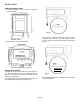
INSTALLATION DAMPER ROD INSTALLATION 1. Locate rectangular cutout on bottom stove panel behind ash pan. Fig. A For initial setup, push the damper all the way in (when facing the front of the stove, “in” is to the left, and “out” is to the right) and slowly pull back three notches (see Fig. B). 2. Screw damper rod into threaded hole. Pulled Back 3 Notches DAMPER ADJUSTMENT The damper rod is located under the bottom plate, on the right hand side of the stove, just behind the ash pan.
INSTALLATION Model T300P Series (viewed from stove back) THERMOSTAT INSTALLATION: NOTE: Always Disconnect Power Before Performing The Thermostat Installation. A 24-volt wall thermostat and 20 feet of 18-gage thermostat wire is included in your stoves accessory package. It is recommended that the thermostat and thermostat wire be installed by an authorized Lennox Hearth Products dealer. Installation Steps: 1. Unplug stove power cord from the wall outlet. 2.
INSTALLATION VENTING REQUIREMENTS It is recommended that only an authorized dealer install your pellet stove. The specified installation requirements must be followed to ensure conformity with both the safety listing of the appliance and local building codes. All clearances, installation instructions and precautions specified by the vent manufacturer must be followed. Selecting a Location - Review the appliance clearance requirements before installing the venting system (see Clearances, page 6).
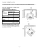
INSTALLATION VENT TERMINATION Do not terminate vent in an enclosed or semi-enclosed area such as: carports, garage, attic, crawl space, under a deck, porch, narrow walkway, closely fenced area, or any location that can build up a concentration of fumes such as a stairwell, covered breezeway, etc. Chimney Height Requirements The vent termination height required is 12” minimum above the roof penetration point as illustrated below (Ref. National Standard, NFPA 7-4.1).
INSTALLATION DETERMINING SIZE OF PIPE TO INSTALL To determine what diameter pipe to use in an installation (3” or 4”), first find the “equivalent pipe length” using the following guidelines, then plot this figure and the altitude on the chart. Fill out the installation chart, and calculate your total equivalent pipe length. After you have the total equivalent pipe length, use the Pipe Selection Chart below to determine if your installation requires 3” or 4” exhaust pipe.
INSTALLATION INSTALLING YOUR PELLET STOVE Standard Horizontal Exhaust Installation (Direct Vent) 1. Locate the proper position for the listed type “PL” wall thimble. Avoid cutting wall studs when installing your pipe. Use a saber saw or keyhole saw to cut the proper diameter hole through the wall to accommodate the wall thimble. Use extreme caution to avoid cutting into power lines within the wall of the home. The hole size will depend on the brand of pellet vent that you are using.
INSTALLATION INSTALLATION CONFIGURATIONS – Standard Horizontal Installations If you vent to the furthest wall, the vent pipe must maintain a 3” clearance parallel to the other wall. Note: Horizontal run of pipe requires 1/4” / 7 mm rise per foot.
INSTALLATION Installation Configurations / Standard Venting Options This appliance may be connected to an existing flue or by installing listed type “PL” vent pipe. If a liner is run all the way to the top of the existing chimney, the existing flue should be sealed with a steel plate. Start a vertical run with a Tee at the back of the stove. Other options are illustrated below. Note: See page 11 for Vent Termination Requirements. Preferred Installation – Vertical Vent Through the Roof.
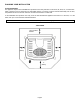
CARE AND OPERATION CONTROL BOARD OPERATION Stove On / Off Button – This button will turn your stove on or off while in Manual or Automatic mode (see page 19 for details). The green on / off light at the top of control board will indicate the on / off status. Heat Output Button – The heat output button has three selection settings, Low, Medium and High. Pressing the button will scroll the red indicator lights from Low to High. The button controls the pellet feed and combustion airflow simultaneously.
CARE AND OPERATION Note: The control board is equipped with an internal memory which will recall the last setting and mode the stove was in prior to loss of power. Because we individually check each stove prior to packaging, one of the two scenarios will appear when you first plug in your stove. 1). The Green LED at the top of the control board will illuminate and the blowers will be running. This is a standard cool down mode and will last no longer than five minutes.
CARE AND OPERATION Combustion Voltage Trim Steps: 1. Push button “twice” for access voltage calibration mode. 2. Identify the current calibration setting indicated by one YELLOW LED bar. 3. Push the “HEAT” control button to adjust setting UP. Each push raises the YELLOW LED bar & increases voltage 5%. 4. Push the “BLOWER” control button to adjust setting DOWN. Each push lowers YELLOW LED bar decreasing voltage 5%. 5. Push the calibration button once to lock in selected results.
CARE AND OPERATION Manual Operation: Pressing the stove ON / OFF switch initiates the start-up cycle. The green ON / OFF light, near the top of the control board, will light up to indicate the “on” status. The fan speeds and pellet feeds are fixed during this time to provide appropriate ignition. The Fast-Fire igniter system will light the pellets feeding to the UltraGrate, after about 3 minutes. The start-up cycle is in effect for approximately 2 minutes after flame is detected in the UltraGrate.
CARE AND OPERATION DAMPER OPERATION The damper is a plate that helps control the amount of airflow supplied for combustion. With the damper pushed in all the way, the airflow is at its minimum. As the damper is pulled out, more air is allowed to flow. It will be necessary to monitor the appearance of the flame during the first 4-8 bags of pellets.
CARE AND OPERATION FUEL REQUIREMENTS Using the UltraGrate burn system, this appliance has been designed to burn wood residue pellets with up to 3% ash content. Agricultural pellets (i.e…corn, alfalfa etc.) are not permitted to be burned in the stove. Dirty fuel will adversely affect the performance of the stove. Caution: The use of unapproved, dirty, wet and / or high salt content fuel will void the warranty! Wood pellets manufactured to the Pellet Fuels Institute (P.F.I.
ROUTINE MAINTENANCE * Inspect your stove or insert at minimum frequency stated until you establish a minimum frequency required for your installation (frequency will vary depending upon fuel BTU value / ash content, usage, and misc. installation variables). ROUTINE CLEANING Note: Stove will need to be shut off and cooled enough to handle before routine cleaning is performed. Always disconnect power before doing any routine cleaning.
ROUTINE MAINTENANCE PHOTOEYE The photoeye is positioned to view the flame from the top of the auger feed tube. It is located below the auger cover and can be accessed from inside the hopper for annual maintenance or replacement (if necessary). Photoeye Access Inside Hopper Using a 11/32" nut driver remove the 3 nuts to access photoeye and filter. Photoeye Cover Plate. Clean Filter Lens: 1. With the photoeye cover plate removed, look inside the opening.
ROUTINE MAINTENANCE Tube Scraper Use the hole in the handle of the grate scraper tool to “grab” onto the rod Clean-Out Tee w/ Cover Removed Remove cover, then remove ash * (Minimum Frequency of 1-2 months) HEAT EXCHANGER TUBES ONLY CLEAN HEAT EXCHANGER TUBES AFTER STOVE HAS COOLED DOWN. A rod is located above the heat exchange baffle (inside of firebox) is used for cleaning the tubes.
ROUTINE MAINTENANCE DOOR ROPE GASKET The condition of the rope gasket around the door and windows should be checked periodically and replaced or repaired if necessary. A one-inch strip of paper may be used to perform a test of the integrity of the door seal. Close the door on the paper in several different locations and pull. It is normal to feel only a slight amount of friction.
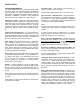
SPECIFICATIONS - Model T300P Series Flue Size 3” / 76mm Rear Width, Overall 28 3/4” / 730 mm Depth, Overall 26 1/2” / 660 mm Height 28 3/4” / 730 mm Floor to Rear Flue Center 8 3/4” / 222 mm Facing Back of Unit, Outside Edge of Left Leg To Center of Rear Flue Outlet 10 1/2” / 267 mm Floor to Rear Outside Air Inlet 10” / 254 mm Facing Back of Unit Outside Edge of Left Leg To Center of Air Inlet 17 1/2” / 445 mm Floor Protection Requirements + Fastfire Self Igniter Wall Thermostat (wire incl
DEFINITIONS AIR WASH To inhibit buildup of soot on the door glass, air is delivered to the glass through an air wash system located in the doorframe surrounding the glass. AUGER It transfers the fuel down the burner tube into the burn grate. AUGER MOTOR Drives the Auger. Motor specifications are: .4 Amp, 1 rpm (revolutions per minute). BLOWER, ROOM AIR (CONVECTION) The blower function is to transfer the heat from the appliance to heat the room air.
WIRING DIAGRAM Page 28
TROUBLESHOOTING (Qualified Technicians Only) Unplug Appliance Before Performing Any Troubleshooting or Maintenance PROBLEM 1. Fire burns with a lazy orange flame. Pellets build up in the grate and the window gets sooted up. CAUSE(S) There is insufficient combustion air. SOLUTIONS Remove any clinkers or ash from the bottom of the grate that might be obstructing the primary air holes. Change to a better grade of fuel if necessary. Check that the damper has been opened enough for the amount of fuel feed.
TROUBLESHOOTING (Qualified Technicians Only) Unplug Appliance Before Performing Any Troubleshooting or Maintenance PROBLEM CAUSE(S) SOLUTIONS 4. Blowers will not operate when the start switch is depressed. There is no power to the stove. Check that the stove is plugged in to the wall outlet. There is no power to the control board. Check to see if your circuit breaker has tripped. 5. There is soot or fly ash in the house. The window is being cleaned when the stove is operating.
REPLACEMENT PARTS LIST Door Parts & Body Components Item # Part # Description 1 20953002 Door Assembly, Black Painted – Model T300P 1 20953012 Door Assembly, Black Enamel – Model T301P 1 20953052 Door Assembly, Green Enamel – Model T305P 1 20953082 Door Assembly, Sand Enamel – Model T308P 26M81 Gasket Kit, Door, 3/4” Rope (10' of 11547) 61057208 Gasket Kit, Glass (4’) 20M44 Cast Top, Black Painted – Model T300P 20M49 Cast Top, Black Enamel - Model T301P 20M54 Cast Top, Green Enamel – Mo
REPLACEMENT PARTS LIST Auger Item # Part # Description 20 12041300 Collar & Screw Set, Auger (3pc.) 21 20950087 End Flange, Auger 22 61050003 End Plate Gasket, Auger (5pc.) 23 11756300 Shaft, Auger Misc.
REPLACEMENT PARTS DIAGRAMS 1 5 9 10 6 2 11 3 7 12 4 8 Page 33
REPLACEMENT PARTS DIAGRAMS 13 18 23 14 24 20 25 15 21 16 27 22 17 Page 34
OPTIONAL ACCESSORIES Note: Install and use accessories per instructions provided with the accessory kit.
INSTALLATION TIPS Page 36
SIMPLE OPERATING INSTRUCTIONS LABEL Page 37
T300P PELLET STOVE SAFETY LABEL Note that your serial number is printed on the safety label located on the back of the stove. Your stove’s serial number is preceded by a “WH-”(Example WH-0000000).
Dealer’s Name: Dealer’s Address: City: State: Zip Code: Serial Number: Date of Purchase: Date Installed: Notes: SERVICE AND MAINTENANCE LOG Service Service Service Date Technician Description Page 39
1110 West Taft Avenue Orange, CA 92865