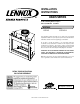
INSTALLATION INSTRUCTIONS OASIS SERIES 43" Wood Burning Outdoor Fireplace P/N 850,015M REV. C 03/2007 MODELS LSO-43 LSO-43-H This installation manual will enable you to obtain a safe, efficient and dependable installation of your fireplace system. Please read and understand these instructions before beginning your installation. Do not alter or modify the fireplace or its components under any circumstances.
TABLE OF CONTENTS Safety Rules .................................... page Tools and Building Supplies ............ page Precautions ..................................... page Introduction ..................................... page Clearances/Height Requirements ..... page Chimney System ............................. page Assembly Outline ............................. page Location of Fireplace ....................... page Assembly Steps ............................... page Preinstallation Notes .............
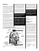
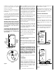
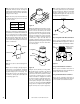
INTRODUCTION General Information The LSO-43 fireplace is a traditional wood burning radiant heat system. The LSO-43-H comes with Herringbone styled refractory. These fireplaces come with standard bar grates, air inlet and optional decorative glass doors. The fireplace is intended to be installed outside of the home. It could be installed against the outside wall of the house, or as a freestanding fireplace on the porch, patio, or simply located in the yard (see Figure 2 ).
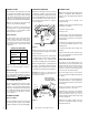
CHIMNEY SYSTEM LOCATION OF FIREPLACE ASSEMBLY STEPS These fireplaces are designed and code listed for use with Security's FTF10 chimney System only. Always use Security's FTF10 chimney components with these fireplaces. Do not modify or alter these components as this may cause a potential serious hazard and void the Warranty. Carefully select the proper location for chimney obstructions, clearance to side wall(s) air inlet location and aesthetics.
3. Note the floor construction, i.e. 2 x 6’s, 2 x 8’s or 2 x 10’s, single or double joists, type and thickness of floor boards. 4. Use this information and consult your local building code to determine if you need additional support. If you plan to raise the fireplace and hearth extension, build the platform assembly then position fireplace and hearth extension on top. Secure the platform to the floor to prevent possible shifting.
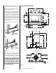
Note: Safety strips are not required when fireplace rests on a noncombustible surface. FIREPLACE SPECIFICATIONS 51 ¹⁄₈" (1299mm) Note: Install the hearth extension only as illustrated (see Figures 41 and 42 ). The safety strips should extend from front of the fireplace at least 1 ¹⁄₂" and should extend to be at least flush with the sides.
Note: The framed depth, 25 ⁵⁄₈" (651 mm) from a framed wall, must always be measured from a finished surface. If a wall covering such as drywall is to be attached to the rear wall, then the framed depth must be measured from the drywall surface. It is important that this dimension be exact. If the appliance is to be elevated above floor level, a solid continuous platform must be constructed. Consult all local codes.
Step 4. The fireplace should be secured to the side framing members through the nailing flange (Figure 16 ). Note: Secure the duct hood to a vertical post with the inlet positioned downward. Ensure that nothing blocks the hood opening. This duct must never terminate higher than 3 feet below the fireplace termination (Figure 18 ).
CHIMNEY 30° OFFSET THROUGH FLOOR OR CEILING It may be necessary to assemble the chimney at 30° when passing through the floor or ceiling area. Use the F10FS30-2 firestop spacer as shown in Figures 20 and 21. Support the chimney at floor or ceiling penetration with a FTF10 stabilizer if distance of chimney below ceiling is 10' or more. Maintain 2" minimum air space to combustibles from chimney sections. F10FS30-2 Firestop Spacer 2" (51mm) Min. Air Space 2" (51mm) Min.
Note: If chimney extends more than 8' above roof surface, guy wires are also recommended. Use three (3) guy wires, attach to locking band assembly, extend and secure to roof in a triangular pattern (Figure 29 ). Guy wires are not supplied by the manufacturer. Note: Do not apply excessive pressure to any subsequent chimney sections following the stabilizer when installing. Ensure each subsequent chimney section is securely attached by testing as noted in Step 3. Step 5.
Note: It is recommended that all exterior exposed metal chimney components; such as terminations, flashings, storm collars and/or flue be painted with a premium quality, high temperature, rust preventative paint designed for metal. This is especially important when installations are made in abnormally adverse or corrosive environments; such as near lakes, oceans or in areas with consistently high humidity conditions. Consult the paint manufacturers instructions for proper preparation and application.
SPECIAL OFFSET INSTRUCTIONS To clear any overhead obstructions, you may offset your chimney system using Security's 30° offset and return elbows. Use two elbows - an offset elbow to initiate the offset and a return elbow to terminate it. A 30° offset elbow, angling in any direction, may be the first component used off the top of the fireplace flue collar.
FTF10 VERTICAL ELEVATION CHART Height Of Chimney Only Inches 11 17 21 27 33 35 37 43 51 55 61 67 69 79 85 89 95 103 113 119 123 129 137 147 153 158 164 171 182 188 192 198 206 215 222 226 232 240 250 256 260 266 274 284 290 294 300 308 318 324 328 334 342 352 358 363 369 376 387 393 397 403 411 421 427 431 437 445 455 ¹⁄₄ ¹⁄₄ ¹⁄₄ ¹⁄₄ ¹⁄₄ ¹⁄₄ ¹⁄₄ ¹⁄₄ ¹⁄₄ ¹⁄₄ ¹⁄₄ ¹⁄₄ ¹⁄₂ ¹⁄₂ ¹⁄₄ ¹⁄₂ ¹⁄₂ ³⁄₄ ³⁄₄ ¹⁄₂ ³⁄₄ ³⁄₄ ³⁄₄ ³⁄₄ ¹⁄₄ ¹⁄₄ ¹⁄₄ ¹⁄₄ ¹⁄₂ ¹⁄₂ ¹⁄₄ ¹⁄₂ ¹⁄₂ ³⁄₄ ³⁄₄ ¹⁄₂ ³⁄₄ ³⁄₄ ³⁄₄ ³⁄₄ ³⁄₄ ³⁄₄ ³⁄₄ ³⁄₄ ¹⁄₄ ¹⁄₄ ¹⁄₄ ¹⁄
FTF10 OFFSET ELEVATION CHART A Offset B Height FTF10-ES30 Offset/Return FTF10-S4 Number of FTF10 Chimney Sections A Offset B Height (Inches) (Inches) Elbow Set Stabilizer 12" 18" 36" (mm) (mm) 1 1 1 1 1 1 1 1 1 1 1 1 1 1 1 1 1 1 1 1 1 1 1 1 1 1 1 1 1 1 1 1 1 1 1 1 1 1 1 1 1 1 0 0 0 0 0 0 0 0 0 0 0 0 0 0 0 0 0 0 0 0 0 0 0 0 0 0 0 0 0 0 0 1 1 1 1 1 1 1 1 1 1 1 0 1 0 2 1 0 0 2 1 1 0 0 2 4 1 3 0 0 2 1 1 3 0 0 2 1 1 0 0 2 1 1 0 2 1 1 0 2 1 3 0 1 0 0 1 0 1 2 0 1 2 0 3 1 0 1 1 0 2 0 1 4 0 1 3 1
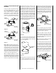
Note: See Framing and Dimension Chart for the sizes of the ceiling and roof openings. The size of the roof opening varies with the degree of pitch of the roof. OPTIONAL EQUIPMENT CONSIDERATIONS Offset Elbow Assembly Always plumb gas line installation per local codes. Check all connections with soap suds; leaks will bubble. Never test any gas line connection with a match or open flame. Offset elbows install the same as chimney sections.
Hearth Extension Dimensions Finished Wall Header Opening Width 43" A 20" (508 mm) B 43" (1092 mm) C 12" (305 mm) D 62" (1575 mm) 12" Min. Spacer C Combustible Mantel 12" Min. * Noncombustible Wall Covering Fireplace Opening C B A D Figure 41 U.S. Installation * A 1¹⁄₂” Projection Is Permitted Between The Face Top And Mantle, 8” Minimum Above Door Opening Figure 40 Hearth Extensions and Wall Shields A hearth extension must be installed with all fireplaces.
Answer - The minimum required thickness of the Micore 160 is .417”, therefore round up to nearest standard thickness available which is 1/2”. Side Wall cannot be Closer than 12" (305mm) under any Circumstances Wall Shield Listed Material k (per inch) Listed Material .84 KL r (per inch) Listed Min.Thickness 1" TL 1.
The sum of all “R values” is: .70 + .10 +. 038 + .10 = .938 This would NOT be an acceptable combination of material for the hearth extension since the total calculated “R value” of the materials used is under the required “R value” of 1.19. An additional layer of insulating materials must be used. Note: Also see NFI Certification Manuals for expanded explanation on calculating “R values” when multiple materials are used.
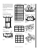
INSTALLATION COMPONENTS Round Termination Firestop Spacer (Flat) Combination Offset/Return Elbow Offset/ Return Package (30°) 63L43 63L36 63L34 63L23 Chimney Section 63L16 63L17 63L18 FTF10-12 FTF10-18 FTF10-36 Chase Termination (Square) 63L52 FTF10-CT2 Flashing 63L40 63L41 F10F6 F10F12 Chase Termination (Round) 63L46 FTF10-CTDT Chase Termination (Square) 63L49 FTF10-CT1 Stabilizer 63L26 FTF10-S4 FTF10-ATT Chase Termination (Open Top) FTF10-CTD F10FS-2 FTF10-OR15 FTF10-ES30 C
LENNOX reserves the right to make changes at any time, without notice, in design, materials, specifications, prices and also to discontinue colors, styles and products. Consult your local distributor for fireplace code information. Printed in U.S.A. © 2002 by LENNOX 20P/N 850,015M REV. C 03/2007 NOTE: DIAGRAMS & ILLUSTRATIONS NOT TO SCALE.