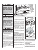
HOMEOWNER'S CARE AND OPERATION INSTRUCTIONS 05 Pr 04 elim -0 in 1- ar y DIRECT VENT SEE-THROUGH MERIT® PLUS SERIES DIRECT-VENT GAS FIREPLACE HEATERS P/N 875,025M REV. NC 04/2005 MODELS WARNING: IF THE INFORMATION IN THIS MANUAL IS NOT FOLLOWED EXACTLY, A FIRE OR EXPLOSION MAY RESULT CAUSING PROPERTY DAMAGE, PERSONAL INJURY OR LOSS OF LIFE. FOR YOUR SAFETY: Do not store or use gasoline or other flammables or liquids in the vicinity of this or any other appliance.
CONGRATULATIONS! In selecting this LENNOX Direct-Vent Gas Appliance you have chosen the finest and most dependable fireplace to be found anywhere. Its a beautiful, prestigious alternative to a wood burning fireplace. Welcome to a Family of tens of thousands of satisfied LENNOX Fireplace Owners. Please carefully read and follow all of the instructions found in this manual. Please pay special attention to the safety instructions provided in this manual.
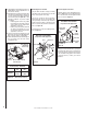
Manifold Gas Supply Pressure (electronic models) Fuel # Fixed Natural Gas 3.5" WC (.87 kPa) Propane 10.0" WC (2.49 kPa) Table 5 Test gauge connections are provided on the front of the millivolt gas control valve, identified IN for the inlet and OUT for the manifold side (see Figure 2 on Page 4 ). A 1/8" NPT Test gauge connection is provided at the inlet and outlet (manifold) ports on the electronic gas control valve (see Figure 3 on Page 5 ).
WARNING Carbon monoxide poisoning: early signs of carbon monoxide poisoning are similar to the flu with headaches, dizziness and/or nausea. If you have these signs, obtain fresh air immediately. Turn off the gas supply to the appliance and have it serviced by a qualified professional, as it may not be operating correctly. Note:The gas supply line must be installed in accordance with building codes by a qualified installer approved and/or licensed as requed by the locality.
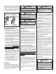
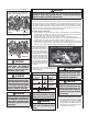
Once the pilot is lit, if your electronic appliance is equipped with an optional burner control switch kit the appliance main burner may be turned on and off using the optional switch (See optional accessories on Page 12 - Wall Switch, Wall Thermostat Or Remote Control Receiver). Honeywell Electronic Gas Valve ON / OFF Switch OFF ON CONTROL IN Manifold Pressure Port Inlet Pressure Port IGNITER PSI WARNING Turn off gas and electrical power before servicing the appliance.
Inspect and clean all wire connections. Ensure that there is no melting or damage. Inspection should include: • Terminals at the Valve • OFF/ON Switch • (Optional Control Switch) Wall Thermostat, Remote Control or Remote Wall Switch Kit Inspect Burner Flame Appearance Ensure that the burner flame appearance resembles the flame shown in Figure 13 and as described in Flame Appearance and Sooting on Page 9. The Homeowner must contact a qualified service technician at once if any abnormal condition is observed.
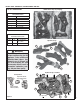
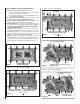
INSTALL GRATE, VERMICULITE, GLOWING EMBERS AND LOGS Bottom View of Logs (in packaging) LOG SET - IDENTIFICATION LOG SET Catalog Number H3210 * Item Description A Log, Center B Log, Left Rear C Log, Left Front D Log, Right Rear E Log, Top Center F Log, Front Center C A B F * Item "letters" above correspond to photos on right D E REFERENCE Firebox Accessories / Parts Cat. No. Model No. 88L53 FGE 42363 Description Bag of Glowing Embers (1 oz.
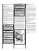
READ LOG WARNINGS ON PAGE 9 BEFORE PROCEEDING 1. Remove front glass enclosure panel from appliance. a. Open Control Compartment Access Panel (see Control Compartment Access Instructions on Page 4.). b. Remove the glass panel enclosure (see Removing Glass Enclosure Panel instructions on Page 6. 2. Remove the following from firebox; log set, embers (rockwool) and vermiculite. Handle logs carefully to prevent breakage. 3.
10. Place Log (E) as shown in Figure 11. Position round end of log (E) against the notch of log (D) here. Two charred spots face the front E D C Position Small End of Log (E) on The Notch of Log (C) Here (Valve Access Side) Figure 11 11. Place Log (F) as shown in Figure 12. Log (F) sits in front of the grate (Valve Access Side) F Figure 12 WARNING This appliance is not designed to burn wood. Any attempt to do so could cause irreparable damage to appliance and prove hazardous to your safety.
2. Light appliance (follow lighting procedure on lighting label in control compartment or see homeowners manual). 3. Allow the burner to operate for at least 15 minutes while observing the flame continuously to ensure that the proper flame appearance has been achieved (see Figure 13 ). If the following conditions are present, adjust accordingly. • If flame appears weak or sooty, adjust the air shutter, incrementally, to a more open position until the proper flame appearance is achieved.
WIRING DIAGRAMS Auxiliary View A J-Box Wiring when using unit mounted relay module. BK W G CAUTION Label all wires prior to disconnection when servicing controls. Wiring errors can cause improper and dangerous appliance operation. Relay Module C/W FBK-250 only. Plug blower into J-Box receptacle for FBK-100 or FBK-200 application. View A for J-Box wiring.
ACCESSORY COMPONENTS Product Reference Information Cat. No. Model Ship. Weight Ship. Volumn H3201 MPD35ST-NM 220 lbs 46W x 26D x 43H (30 cu.ft.) H3202 MPD35ST-PM 220 lbs 46W x 26D x 43H (30 cu.ft.) H3203 MPD35ST-NE 220 lbs 46W x 26D x 43H (30 cu.ft.) Remote Control Kit, Standard Cat. No. Model No. H0249 RCL Description Remote Control System (Standard) (ref.
Note: Door & Trim Kits are for 1 side only. If set is desired, order 2 kits. ACCESSORY COMPONENTS Arch Design 2-Piece Louver Kits Arch Pane Design 3 Piece Trim Kit Cat. No. Model No. Description Cat. No. Model No. Description 96L05 2LVR35PB 2 Pc. Louver Kit, Polished Brass 96K21 TK35PB3 35” 3 Piece Finish Trim Kit, Polished Brass 96L09 2LVR35BS 2 Pc. Louver Kit, Brushed Stainless (ref. Form # 750,147M) Polished Brass 3-Piece Trim Kit (ref.
ACCESSORY COMPONENTS * 35" Eyebrow Hood Kits Cat. No. Model No. 96K67 EB35PB Hood Kit, Polished Brass EB35BS Hood Kit, Brushed Stainless 88L49 Description Model No. Description Cat. No. Model No. HG35M 35" Screen Heat Guard Kit 26M43 ADK35CMPB Arch Door, Polished Brass * Order 2 for set if desired. 26M44 ADK35CMBS Arch Door, Brushed Stainless (ref. Form # 750,101M) * Order 2 for set if desired. Cat. No.
LIGHTING INSTRUCTIONS – MILLIVOLT GAS VALVE FOR YOUR SAFETY READ BEFORE LIGHTING WARNING: IF YOU DO NOT FOLLOW THESE INSTRUCTIONS EXACTLY, A FIRE OR EXPLOSION MAY RESULT CAUSING PROPERTY DAMAGE, PERSONAL INJURY OR LOSS OF LIFE. • Do not use any phone in your building. • Immediately call your gas supplier from a neighbor’s phone. • If your gas supplier cannot be reached, call the fire department. A. This appliance has a pilot which must be lit with a piezo igniter.
LIGHTING INSTRUCTIONS — ELECTRONIC FOR YOUR SAFETY READ BEFORE LIGHTING WARNING: IF YOU DO NOT FOLLOW THESE INSTRUCTIONS EXACTLY, A FIRE OR EXPLOSION MAY RESULT CAUSING PROPERTY DAMAGE, PERSONAL INJURY OR LOSS OF LIFE. A. When lighting the appliance, follow these instructions exactly. B. BEFORE OPERATING smell all around the appliance area for gas. Be sure to smell next to the floor because some gas is heavier than air and will settle on the floor.
MAINTENANCE SCHEDULE Annually (Before the onset of the Burning Season) MAINTENANCE TASK ACCOMPLISHING PERSON PROCEDURE Inspecting/Cleaning Burner, Logs and Controls Qualified Service Technician Inspect valve and ensure it is properly operating. Check piping for leaks. Vacuum the control compartment, fireplace logs and burner area.
TROUBLESHOOTING Note: Before troubleshooting the gas control system, Ensure external gas shut off valve, located at gas supply inlet, (and wall switch, iff applicable), is in the “ON” position. Important: Valve system troubleshooting should only be accomplished by a qualified service technician. TROUBLESHOOTING GUIDE - MILLIVOLT GAS CONTROL SYSTEM SYMPTOM POSSIBLE CAUSES 1. Spark igniter will not light pilot after repeated triggering of igniter button. 2.
TROUBLESHOOTING PROCEDURE - ELECTRONIC IGNITION SYSTEM START CHECK • Turn Off Gas Supply. • Ensure Valve Switch Is In ON Position. • Disconnect Control Harness. • Set Thermostat To Call For Heat. • Check for proper voltage at control harness (see insert A). Voltage NO 2 should be 24V between thermostat or pressure switch and 24V common and 24V hot.
REPLACEMENT PARTS - MPD35ST Item Part/Cat.No. Qty Description Item Where Used Part/Cat. Qty SIT Millivolt Only 1 H3357 1 Gas Train Assembly, NG, MV MPD35ST-NM 1 H3355 1 Gas Train Assembly, LP, MV MPD35ST-PM H3210 14 H3356 3 1 42J32 1 Log Set All All All 15 LB-92449B 2 Louver Assembly, Upper Charcoal Gas Train Assembly, NG, Elecrtr.