
User Guide


NOTE: DIAGRAMS & ILLUSTRATIONS ARE NOT TO SCALE.
5
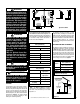
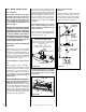
Figure 2
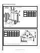
Figure 3
*Note: See Page 6, Step 1 for clearance
requirements to the nailing flange located at
each side of the unit and any screw heads
adjacent to it.
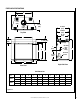
The appliance should be mounted on a fully
supported base extending the full width and
depth of the unit. The appliance may be located
on or near conventional construction materials.
However, if installed on combustible materials,
such as carpeting, vinyl tile, etc., a metal or
wood barrier covering the entire bottom surface
must be used.
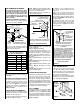
APPLIANCE AND VENT CLEARANCES
The appliance is approved with zero clearance to
combustible materials on all sides (as detailed
in Table 5), with the following exception: When
the unit is installed with one side flush with a
wall, the wall on the other side of the unit must
not extend beyond the front edge of the unit. In
addition, when the unit is recessed, the side walls
surrounding the unit must not extend beyond
the front edge of the unit. See Figure 2.
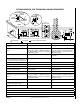
LOCATION
In selecting the location, the aesthetic and func-
tional use of the appliance are primary concerns.
However, vent system routing to the exterior and
access to the fuel supply are also important.
Consideration should be given to traffic ways,
furniture, draperies, etc., due to elevated surface
temperatures (Figure 2). The location should
also be free of electrical, plumbing or other
heating/air conditioning ducting.
HORIZONTAL VENT
VERTICAL VENT
CROSS CORNER
APPLICA
TION
RECESSED
APPLICATION
FLA
T
APPLICA
TION
ROOM DIVIDER
APPLICA
TION
FLA
T ON W
ALL
APPLICA
TION
ISLAND
APPLICA
TION
Typical Locations
Shelf Height
(
see table)
Do not insulate the
space between the
appliance and the
area above it.
Shelf Above Fireplace With Top Venting
2 Foot
Vertical
Vent
(Min.)
APPLIANCE MINIMUM CLEARANCES*
Inches (millimeters)
Back 1/2 (13)
0 (0) Spacers
Sides 1/2 (13)
0 (0) Spacers
Top Spacers 0 (0)
Floor 0 (0)
Bottom of Appliance
To Ceiling
69 (1743)
Table 5
MINIMUM VENTING CLEARANCES
Inches (millimeters)
Vertical Sections
Sides 1" (25 mm)
Horizontal Sections
Top 3" (75 mm)
Bottom 1" (25 mm)
Sides 1" (25 mm)
Vertical Vent Applications
Sides 1" (25 mm)
Table 4
Model No.
Combustible Shelf Height
Inches (millimeters)
Top Vent - with 2 Feet Vertical Vent
and One 90 Degree Elbow
Secure Vent
LSM40-2 *84-1/16 (2135)
LSM45-2 89-1/16 (2252)
* Includes 3” clearance to combustibles
(required above vent components)
WARNING
Failure to comply with the instal-
lation and operating instructions
provided in this document will
result in an improperly installed
and operating appliance, voiding
its warranty. Any change to this
appliance and/or its operating
controls is dangerous. Improper
installation or use of this appli-
ance can cause serious injury or
death from fire, burns, explosion
or carbon monoxide poisoning.
WARNING
Children and adults should be
alerted to the hazards of high
surface temperatures. Use
caution around the appliance
to avoid burns or clothing igni-
tion. Young children should be
carefully supervised when they
are in the same room as the
appliance.
Note: An Optional Screen Door
or Screen Panel for the glass is
available (see Care and Opera-
tions Manual for ordering infor-
mation).
Do not insulate the space between the appli-
ance and the area above it. See Figure 3. The
minimum height from the base of the appliance
to the underside of combustible materials used
to construct a utility shelf in this fashion is
shown in the table in Figure 3.
WARNING
Do not place clothing or other
flammable materials on or near
this appliance.
AVERTISSEMENT
Surveiller les enfants. Garder les
vêtements, les meubles, l'essence
ou autres liquides à vapeur inflam-
mables lin de l'appareil.