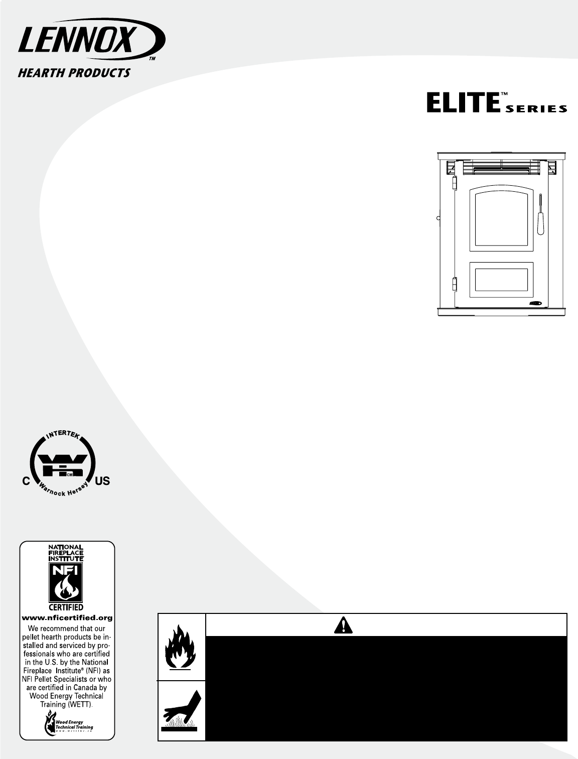
INSTALLATION AND OPERATION MANUAL Free-Standing Pellet Stove Save These Instructions For Future Reference P/N 775,196M, Rev. NC, 06/2008 Pellet Stove Model Montage™ 32FS A French manual is available upon request. Order P/N 775,196CF. Ce manuel d’installation est disponible en francais, simplement en faire la demande. Numéro de la pièce 775,196CF. Report No. 3105656MID These appliances must be properly installed and operated in order to prevent the possibility of a house fire.
IMPORTANT SAFETY AND WARNIING INFORMATION read THIS MANUAL IN ITS ENTIRETY and understand these Rules to follow for safety. WARNING Improper installation, adjustment, alteration, service or maintenance can cause injury or property damage. Refer to this manual. For assistance or additional information consult a qualified installer or service agency. WARNING Do not attempt to alter or modify the construction of the appliance or its components.
Congratulations! Testing / Listing When you purchased your new pellet stove, you joined the ranks of thousands of individuals whose answer to their home heating needs, aesthetics, efficiency and our environment. We extend our continued support to help you achieve the maximum benefit and enjoyment available from your new pellet stove. Listing: The listing laboratory is ITS (Intertek Testing Services) and the listing mark is Warnock Hersey.
Power Supply Requirements These requirements must be met unless otherwise specified by state or local authorities. • Power Cord - The power cord must be plugged into a standard, 120 Volt, 60 Hz grounded electrical outlet with proper ground and polarity. The power cord must be routed to avoid contact with any of the hot or sharp exterior surface areas of the stove. • Power Supply - 575 Watts, and will peak up to 782 Watts during the 30 minute cycle when igniter is operating.
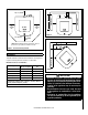
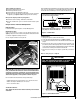
Rear Wall or Alcove Combustible Up to * 6” (153 mm) 6” (153 mm) min. 6” (153 mm) min. Top View Combustible D E A A Combustible B Rear Front Figure 2 Floor Protector 6” (153 mm) min. Corner Combustible *Note: When installed at clearances less than 6”, the floor protection is only required to extend to the wall.
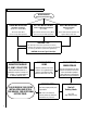
INSTALLATION TIPS INSTALLATION TIPS Select Your Installation Type GOOD INSTALLATION: BETTER INSTALLATION: Horizontal Installation (Direct Vent - Outside Wall) BEST INSTALLATION: Vertical & Horizontal Installation (Up and Out) Vertical Installation (Straight Up) No natural draft. Wind pressures may affect operation Some natural draft aids venting.
MANUFACTURED HOME INSTALLATION In addition to the standard installation instructions, the following instructions may be required by local, state or federal building codes: • Installation should be in accordance with the Manufactured Home and Safety Standard (HUD), CFR 3280, Part 24. • The stove must be permanently bolted to the floor using two or three 1/4" or 5/16" Ø x 5" lag screws as shown in Figures 4A, 4B, 5A and 5B.
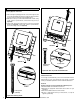
INSTALLATION Removing Appliance From Pallet 1. After removing the packaging from the stove, lift the hopper lid, and remove all prepackaged items that were shipped in the hopper. Next, open the stove door and remove all prepackaged items. 2. With the stove door open, remove the ash drawer and set aside. Using a 7/16” socket or open end wrench, remove the front lag screw (see Figure 5A). 3. Using a 5/32" allen wrench remove the two screws in the rear pallet bracket (see Figure 5B).
Prior to lighting your appliance: q Review the safety precautions section. q Review the pellet FUEL section. q Review and follow the Operating Instructions. q Plug power cord connector into corresponding connector on the back of appliance (see Figures 7 and 8 showing connector locations). A 24 volt wall thermostat and 20 feet of 18-gage thermostat wire is included in the accessory package. It is recommended that the thermostat and thermostat wire be installed by an Lennox Hearth Products dealer.
VENTING REQUIREMENTS It is recommended that only an Lennox Hearth Products dealer install your pellet stove. The specified installation requirements must be followed to ensure conformity with both the safety listing of the appliance and local building codes. All clearances, installation instructions and precautions specified by the vent manufacturer must be followed. Silicone sealant and 3 screws are required to secure the first vent connection to the appliance flue collar.
Vent Termination Locations Air Supply Inlet Vent Terminal Area Where Terminal Is Not Permitted Vertical Terminal 24” (610mm) Vertical Terminal G (From Eave) 24” (610mm) A D E Fixed Closed B B M H N C B B L K J F A B A = Clearance above grade, veranda, porch, deck, or balcony (min. 12”/30cm) B = Clearance to window or door that may be opened (min. 12”/30cm above - 48”/1.2m below and to the side) C = Clearance to permanently closed window *(min.
Chimney Height Requirements - Site Built Residential Home The vent termination height required is - USA, 1-foot minimum; Canada 3-feet minimum above the roof penetration point as illustrated below (Ref. USA - National Standard, NFPA 211 and Canada National Standard CSA B365-01. Check with your local building official for additional requirements for your area.
Determining Size Of Pipe To Install To determine what diameter pipe to use in an installation (3” or 4”), first find the “equivalent pipe length” using the following guidelines, then plot this number and the altitude on the chart (Figure 13). Fill out the installation chart, and calculate your total equivalent pipe length. After you have the total equivalent pipe length, use the Pipe Selection Chart below to determine if your installation requires 3” or 4” exhaust pipe.
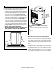
Standard Horizontal Vent Installation 3. Push the stove with pipe attached towards the wall (the pipe will go through the wall thimble). Do not position the back of the stove closer than 2” (51 mm) from the wall (see Clearances, Page 5). Installing Montage™ 32FS All PL Venting Components must be listed to UL 641 or ULC S609 1. Locate the proper position for the listed type “PL” wall thimble. Avoid cutting wall studs when installing your pipe.
Standard Horizontal Installation Configurations Montage™ 32FS 3” (75 mm) Minimum clearance between wall and pipe. If you vent to the furthest wall, the vent pipe must maintain a 3” clearance parallel to the other wall. Top View Illustration 1" Min. Wall Notes: • It is not recommended to terminate exhaust vent on the prevailing wind side of the house. 1" Min. Wall Figure 16 - Montage 32FS, Corner Through the Wall Note: Horizontal run of pipe requires 1/4” (7 mm) rise per foot.
Preferred Installation – Vertical Vent Through the Roof Standard Vertical Installation Configurations Montage™ Model: 32FS This free-standing model may be connected to an existing flue or by installing listed type “PL” vent pipe. If a liner is run all the way to the top of the existing chimney, the existing flue should be sealed with a steel plate. Start a vertical run with a Tee at the back of the stove. Other options are illustrated below.
CARE AND OPERATION Simple Operating Instructions 1. Start FIRST TIME USE 2. Preparation a] Check hopper and remove any materials from hopper and auger 3.
Control Board Operation START BUTTON The "START" Button turns on the pellet stove. If the exhaust does not reach operating temperature within 30 minutes, the stove will automatically shut down. The pellet stove can be restarted by pushing the "START" Button again. RESTART AUGER ON (green LED) - The auger restarts and returns to delivering fuel to the UltraGrate™. STOP BUTTON Note: The "START" Button has to be activated to give power to the AUGER ON/OFF button. The "STOP" button turns the pellet stove OFF.
Pre-lighting Instructions General Operating Considerations During an initial start-up, or in the case where the hopper has run out of fuel, it will be necessary to prime the auger feed system. Proper Burn Characteristics: Your flame should be bright yellow under normal operations. If your flame becomes reddish/orange, your stove probably needs routine maintenance.
Turning Off Your Stove Press the "STOP" button to initiate the shut down cycle (auger LED will be red). The pellets will stop feeding and the blowers will continue to run on a timed cycle. The stove will shut down safely upon completion of the shut down cycle. Shutdown Mode - When the thermostat opens (not calling for heat), or the auger "STOP" button is pressed (feeding LED will be off), power to auger motor will be discontinued.
FUEL Fuel Specifications - Using the Ultragrate™ burn system, this appliance has been designed to burn wood residue pellets only (with up to 3% ash content). Agricultural pellets (i.e. corn, alfalfa etc.) are not permitted to be burned in the stove. Dirty fuel will adversely affect the performance of the stove. The pellet fuel should meet P.F.I. (Pellet Fuel Institute) standards for standard grade or premium grade residential pellet fuel.
Heat Exchange Tubes Tube Scraper - Using the hole in the handle of the Grate Scraper Tool “grab” the scraper rod as shown in Figure 26. Using the Grate Scraper Tool, pull the rod up and out towards the opening of the firebox. Continue pulling until the Tube Scraper reaches the top of the firebox. Pull the tube scraper out, then repeat 2–3 times to remove fly-ash from the heat exchange tubes.
Ash Clean-out Ports (Recommended Frequency of 2 days – 2 weeks) IMPORTANT NOTES: • ENSURE APPLIANCE IS COLD BEFORE BEGINNING. • FIREBRICK PANEL MUST BE INSTALLED BEFORE OPERATING UNIT. • ASH CLEAN-OUT PORTS MUST BE CLEANED OUT AS PART OF ROUTINE MAINTENANCE. Accessing Ash Clean-Out Ports Figure 26 - Pulling Tube Scraper Rod Proof of Fire Switch This switch needs to be removed and cleaned after every 100 bags of fuel burned.
UltraGrate™ (Burn Grate) Ash Pan Inspect the UltraGrate periodically so that the air holes don't clog with ash or clinkers. The UltraGrate can easily be cleaned with the grate scraper tool, or it can be removed. It is very important to monitor the ash build up under the UltraGrate, as too much of ash will block combustion air from entering the grate, causing pellets to pile-up in the grate.
Door Rope Gasket Motor Lubrication The condition of the rope gasket around the door and windows should be checked periodically and replaced or repaired if necessary. The door gasket does not need to be “tight” in all areas, since a small amount of leakage is not hazardous or detrimental to the performance of your stove. The blowers are permanently lubricated by the manufacturer. Do not apply oil to any part of the blower, doing so may cause damage.
SPECIFICATIONS - Montage™ 32FS Product Reference Information Cat. No. Model Ship. Weight Ship. Volume H6839 Montage 32FS 285 lb. 22.06 cu. ft. Flue Size 3” (76 mm) Rear Floor Protection Requirements Front and Sides: 6”(152 mm) Back: Up to 6”(152 mm) u Hopper Capacity 55 Lbs.
COMPONENT DEFINITIONS • Air Wash A small slot in the door that allows room air to be pulled into the firebox and pours over the inside surface of the door glass to inhibit the build up of soot. • Auger A motor powered screw device that transfers the fuel from the hopper to the feed chute to deliver pellets to the UltraGrate™. • Auger Motor Drives the Auger. Motor specifications are: 0.5 Amp, 1.25 RPM (revolutions per minute).
TROUBLESHOOTING Qualified Technicians Only Unplug Appliance Before Performing Any Troubleshooting or Maintenance PROBLEM CAUSE(S) SOLUTIONS 1. Fire burns with a lazy orange flame. Pellets build up in the and there is excessive glass soot that is difficult to remove (Ash and soot are a product of combustion with any wood products, so some build-up on the glass is normal). A) • There is insufficient combustion air. • Fuel feed rate is too high.
TROUBLESHOOTING Qualified Technicians Only Unplug Appliance Before Performing Any Troubleshooting or Maintenance PROBLEM CAUSE(S) SOLUTIONS 4. Blowers will not operate when the ON/OFF start button is depressed. A) There is no power to the stove. A) Check that the stove is plugged in to the wall outlet. B) There is no power to the control board. B1) Check if the house circuit breaker has tripped.
REPLACEMENT PARTS LIST - Montage™ 32FS Contact an Authorized Lennox Hearth Products dealer to obtain any of these parts. Never use substitute materials. Use of nonapproved parts can result in poor performance and safety hazards. DOOR PARTS Item # Cat. No. 1 H7045 Door Assembly 2 H7046 Face Assembly 3 H7047 Door Handle Assembly 4 H7048 Hinge Plate Assembly 5 H7049 Latch Plate Assembly 6 H7313 Door Rope Kit, 4 ft. 7 8 Description 12050506 Door Hinge Pin (2 per pkg.
REPLACEMENT PARTS LIST - Montage 32FS 46 33 13 19 47 34 9 20 5 15 12 21 50 16 18 14 52 11 17 4 49 10 38 ADD WALL THERMOSTAT 39 WIRE, THERMOSTAT 48 ADD PAINT TOUCH UP 52 ADD CLEANING BRUSH 38 7 6 1 Includes 20 feet of thermostat wire 3 52 2 8 31
REPLACEMENT PARTS DIAGRAMS 36 29 30 24 25 37 28 54 40 23 53 32 56 42 28 55 26 44 35 27 45 41 31 34 26 22 27 32 43 31 2831 ADD IN WIRING HARNESS 32 NOTE: DIAGRAMS & ILLUSTRATIONS ARE NOT TO SCALE 33
OPTIONAL ACCESSORIES Item # Cat. No.
ACCESSORIES 4 5 6 PA I N T 7 Form # 775,077M Gothic Accessory Kit, Montage 32FS, Black Paint Form # 775,201M 34 NOTE: DIAGRAMS & ILLUSTRATIONS ARE NOT TO SCALE
safety / listing label Manufactured By / Fabriqué Par: LENNOX HEARTH PRODUCTS PO BOX 987 Auburn, WA 98071 USA CERTIFIED FOR U.S. AND CANADA. LISTED ROOM HEATER FOR Report No./Numéro de Rapport: 3105656MID USE WITH PFI APPROVED PELLETIZED WOOD FUEL ONLY. FOR (Test Date OCT 2006 / Testé le OCT 2006) USE IN MANUFACTURED (MOBILE) HOMES. Serial No. INSTALL AND USE ONLY IN ACCORDANCE WITH THE MANU FACTURER’S INSTALLATION INSTRUCTIONS.
Warranty Your pellet stove is covered by a limited warranty (provided with appliance). Please read the warranty to be familiar with its coverage. Retain this manual. File it with your other documents for future reference. Product reference information We recommend that you record the following important information about your fireplace. Please contact your Lennox Hearth Products dealer for any questions or concerns. For the number of your nearest Lennox Hearth Products dealer, please call 1-800-9-LENNOX.