INSTALLATION INSTRUCTIONS ML193DF 2010 Lennox Industries Inc. Dallas, Texas, USA MERIT® SERIES GAS FURNACE DOWNFLOW AIR DISCHARGE 506475−01 01/2011 Supersedes 10/2010 Litho U.S.A. THIS MANUAL MUST BE LEFT WITH THE HOMEOWNER FOR FUTURE REFERENCE This is a safety alert symbol and should never be ignored. When you see this symbol on labels or in manuals, be alert to the potential for personal injury or death.
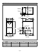
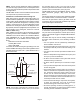
ML193DF Unit Dimensions − inches (mm) 9/16 (14) COMBUSTION AIR INTAKE RETURN AIR OPENING B EXHAUST AIR OUTLET 2−1/16 (52) 5 (127) TOP VIEW 27−3/4 (705) 1 (25) Front Panel A 19−7/16 (494) 9/16 (14) B AIR 9/16 (14) 2−1/4 (57) 9/16 (14) FLOW ELECTRICAL INLET (Either Side) 33 (838) 2 (51) Either Side CONDENSATE TRAP CONNECTION (Either Side) GAS PIPING INLET (Either Side) 9−1/8 (232) Right 6−9/16 (167) Left 3/4 (19) C Supply Air 6−1/2 (165) Either Side 19−1/4 Supply (489) Air 3/4 (19) FRON
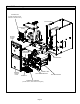
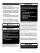
ML193DF Parts Arrangement CONTROL BOX (Includes integrated control, transformer and door switch) BAG ASSEMBLY BLOWER MOTOR (hidden) BLOWER ACCESS PANEL COMBUSTION AIR INDUCER BLOWER DECK PRIMARY LIMIT BURNER ACCESS PANEL COLD END HEADER BOX HEAT EXCHANGER GAS VALVE BURNER BOX ASSEMBLY (includes sensor, rollout switches and ignitor) FIGURE 1 Page 3
ML193DF Gas Furnace The ML193DF Category IV gas furnace is shipped ready for installation in the downflow position. The furnace is equipped for installation in natural gas applications. A conversion kit (ordered separately) is required for use in propane/LP gas applications. The ML193DF can be installed as a Direct Vent or Non− Direct Vent gas central furnace. NOTE − In Direct Vent installations, combustion air is taken from outdoors and flue gases are discharged outdoors.
NOTE − Furnace must be adjusted to obtain a temperature rise within the range specified on the unit nameplate. Failure to do so may cause erratic limit operation and premature heat exchanger failure. This ML193DF furnace must be installed so that its electrical components are protected from water.
General These instructions are intended as a general guide and do not supersede local codes in any way. Consult authorities having jurisdiction before installation. In addition to the requirements outlined previously, the following general recommendations must be considered when installing a ML193DF furnace: • Place the furnace as close to the center of the air distribution system as possible. The furnace should also be located close to the chimney or vent termination point.
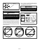
All gas-fired appliances require air for the combustion process. If sufficient combustion air is not available, the furnace or other appliance will operate inefficiently and unsafely. Enough air must be provided to meet the needs of all fuel−burning appliances and appliances such as exhaust fans which force air out of the house. When fireplaces, exhaust fans, or clothes dryers are used at the same time as the furnace, much more air is required to ensure proper combustion and to prevent a downdraft.
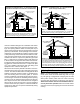
EQUIPMENT IN CONFINED SPACE − ALL AIR FROM OUTSIDE (Inlet Air from Crawl Space and Outlet Air to Ventilated Attic) VENTILATION LOUVERS (Each end of attic) ROOF TERMINATED EXHAUST PIPE EQUIPMENT IN CONFINED SPACE − ALL AIR FROM OUTSIDE (All Air Through Ventilated Attic) ROOF TERMINATED EXHAUST PIPE VENTILATION LOUVERS (Each end of attic) OUTLET AIR OUTLET AIR SIDE WALL TERMINATED EXHAUST PIPE (ALTERNATE LOCATION) INLET AIR VENTILATION LOUVERS (For unheated crawl space) NOTE−The inlet and outlet air o
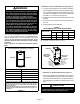
Allow for clearances to combustible materials as indicated on the unit nameplate. Minimum clearances for closet or alcove installations are shown in figure 11. ML193DF09048C BLOWER MOTOR RIGID LEG remove shipping bolt and washer WARNING Blower access panel must be securely in place when blower and burners are operating. Gas fumes, which could contain carbon monoxide, can be drawn into living space resulting in personal injury or death.
Installation on Non−Combustible Flooring Figure 12 WARNING 1 − Cut floor opening keeping in mind clearances listed on unit rating plate. Also keep in mind gas supply connections, electrical supply, flue and air intake connections and sufficient installation and servicing clearances. See table 1 for correct floor opening size. 2 − Flange warm air plenum and lower the plenum into the opening. 3 − Set the unit over the plenum and seal the plenum to the unit. 4 − Ensure that the seal is adequate.
TABLE 2 COMBUSTIBLE FLOORING BASE OPENING SIZE Cabinet Width Catalog Number B Cabinet (17.5") C Cabinet (21") Front to Rear Side to Side in. mm in.
Filters Pipe & Fittings Specifications This unit is not equipped with a filter or rack. A field−provided filter is required for the unit to operate properly. Table 3 lists recommended filter size. A filter must be in place whenever the unit is operating. TABLE 3 Furnace Cabinet Width Filter Size 17−1/2" 16 x 25 x 1 (1) All pipe, fittings, primer and solvent cement must conform with American National Standard Institute and the American Society for Testing and Materials (ANSI/ASTM) standards.
Low temperature solvent cement is recommended during cooler weather. Metal or plastic strapping may be used for vent pipe hangers. Uniformly apply a liberal coat of PVC primer for PVC or use a clean dry cloth for ABS to clean inside socket surface of fitting and male end of pipe to depth of fitting socket. IMPORTANT ML193DF exhaust and intake connections are made of PVC. Use PVC primer and solvent cement when using PVC vent pipe.
Venting Practices Joint Cementing Procedure All cementing of joints should be done according to the specifications outlined in ASTM D 2855. Piping Suspension Guidelines SCHEDULE 40 PVC − 5’ all other pipe* − 3’ NOTE − A sheet metal screw may be used to secure the intake pipe to the connector, if desired. Use a drill or self tapping screw to make a pilot hole. DANGER * See table 4 for allowable pipe.
2 − When furnace is installed in a residence where unit is shut down for an extended period of time, such as a vacation home, make provisions for draining condensate collection trap and lines. Use the following steps to correctly size vent pipe diameter. Exhaust Piping (Figures 20 and 21) 045, 070, 090, 110 or 135 btuh 1 Route piping to outside of structure. Continue with installation following instructions given in piping termination section.
TABLE 7 Maximum Allowable Intake or Exhaust Vent Length in Feet *Size intake and exhaust pipe length separately. Values in table are for Intake OR Exhaust, not combined total. Both Intake and Exhaust must be same pipe size. Standard Termination at Elevation 0 − 10,000 ft.
TYPICAL EXHAUST PIPE CONNECTIONS Pipe size determined in table 7. 2” 2” 2” 2” 2” or 3” TRANSITION *2” DO NOT transition from smaller to larger pipe size in horizontal runs of exhaust pipe. INTAKE EXHAUST TOP VIEW * When transitioning up in pipe size, use the shortest length of 2” PVC pipe possible. NOTE − Exhaust pipe and intake pipe must be the same diameter. FIGURE 20 TYPICAL INTAKE PIPE CONNECTIONS Pipe size determined in table 7.
Intake Piping The ML193DF furnace may be installed in either direct vent or non−direct vent applications. In non−direct vent applications, when intake air will be drawn into the furnace from the surrounding space, the indoor air quality must be considered. Guidelines listed in Combustion, Dilution and Ventilation Air section must be followed. Follow the next two steps when installing the unit in Direct Vent applications, where combustion air is taken from outdoors and flue gases are discharged outdoors.
VENT TERMINATION CLEARANCES FOR NON−DIRECT VENT INSTALLATIONS IN THE USA AND CANADA INSIDE CORNER DETAIL G H A D E B L Fixed Closed Operable F B B C Operable Fixed Closed I M B K J A B VENT TERMINAL A= Clearance above grade, veranda, porch, deck or balcony B= Clearance to window or door that may be opened C= Clearance to permanently closed window D= Vertical clearance to ventilated soffit located above the terminal within a horizontal distance of 2 feet (mm) from the center line of t
VENT TERMINATION CLEARANCES FOR DIRECT VENT INSTALLATIONS IN THE USA AND CANADA INSIDE CORNER DETAIL G H A D E B L Fixed Closed Operable F B B C I Fixed Closed Operable M B K J A B VENT TERMINAL A= Clearance above grade, veranda, porch, deck or balcony B= Clearance to window or door that may be opened C= Clearance to permanently closed window D= Vertical clearance to ventilated soffit located above the terminal within a horizontal distance of 2 feet (mm) from the center line of the
Details of Intake and Exhaust Piping Terminations for Direct Vent Installations NOTE − In Direct Vent installations, combustion air is taken from outdoors and flue gases are discharged to outdoors. NOTE − Flue gas may be slightly acidic and may adversely affect some building materials. If any vent termination is used and the flue gasses may impinge on the building material, a corrosion−resistant shield (minimum 24 inches square) should be used to protect the wall surface.
B B D D C Intake C 3 1 Front View of Intake and Exhaust A Exhaust A 2 Intake Exhaust D TABLE 9 1 E 2" (51mm) Vent Pipe B A− Clearance above grade or average snow accumulation 12" C 2 A B−Horizontal separation between intake and exhaust C−Minimum from end of exhaust to inlet of intake D−Exhaust pipe length E−Wall support distance from top of each pipe (intake/exhaust) 1 The 12" (508MM) Min. 3" (76mm) Vent Pipe 12" (508MM) Min. 6" (152MM) Min. 6" (152MM) Min.
FIELD SUPPLIED WALL TERMINATION OR (15F74) WALL RING TERMINATION KIT With INTAKE ELBOW FIELD SUPPLIED WALL TERMINATION OR (15F74) WALL RING TERMINATION KIT NOTE − FIELD PROVIDED REDUCER MAY BE REQUIRED TO ADAPT LARGER VENT PIPE SIZE TO TERMINATION NOTE − FIELD PROVIDED REDUCER MAY BE REQUIRED TO ADAPT LARGER VENT PIPE SIZE TO TERMINATION 1/2" (13mm) ARMAFLEX INSULATION IN UNCONDITIONED SPACE 1/2" (13mm) ARMAFLEX INSULATION IN UNCONDITIONED SPACE SIZE TERMINATION PER TABLE 8 SIZE TERMINATION PER TABLE
1−1/2" (38mm) accelerator provided on 71M80 & 44W92 kits for ML193DF045P36B− & 070P36B 12” (305mm) SIZE TERMINATION PIPE PER TABLE 8. INTAKE AIR FLASHING (Not Furnished) INTAKE Minimum Above Average Snow Accumulation EXHAUST VENT Front View Top View SHEET METAL STRAP (Clamp and sheet metal strap must be field installed to support the weight of the termination kit.
WALL TERMINATION KITS (CLOSE−COUPLE) EXTENDED VENT FOR GRADE CLEARANCE 2 inch (51 mm) 22G44 (US) 3 inch (76 mm) 44J40 (US) If intake and exhause pipe is less than 12 in. (305 mm) above snow accumulation or other obstructions, field− fabricated piping must be installed. WALL SUPPORT* FIELD−PROVIDED REDUCER MAY BE REQUIRED TO ADAPT LARGER VENT PIPE SIZE TO TERMINATION 8” (203 mm) Min. for 2” (51 mm) & 3” (76 mm) DIA. pipe between the end of the exhaust pipe and intake pipe 12” (305 mm) Max.
ML193DF DIRECT VENT APPLICATION STRAIGHT−CUT OR USING EXISTING CHIMNEY ANGLE−CUT IN DIRECTION SIZE TERMINATION PIPE PER TABLE 8. OF ROOF SLOPE * 8" − 12" (203mm − 305mm) Minimum 12" (305MM) above chimney top plate or average snow accumulation 3" − 8" (76mm− 203mm) INTAKE PIPE INSULATION (optional) 12" (305mm) ABOVE AVE.
12" (305mm) MAX. for 2" (51mm) 20" (508mm) MAX. for 3" (76mm) UNCONDITIONED SPACE 6" (152mm) Max NOTE − If necessary the condensate trap may be installed up to 5´ away from the furnace. Use PVC pipe to connect trap to furnace condensate outlet. Piping from furnace must slope down a minimum of 1/4" per ft. toward trap. SIZE TERMINATION PIPE PER TABLE 8.
5 − If unit will be started immediately upon completion of installation, prime trap per procedure outlined in Unit Start−Up section. Condensate line must slope downward away from the trap to drain. If drain level is above condensate trap, condensate pump must be used. Condensate drain line should be routed within the conditioned space to avoid freezing of condensate and blockage of drain line. If this is not possible, a heat cable kit may be used on the condensate trap and line.
TRAP / DRAIN ASSEMBLY USING 1/2" PVC OR 3/4" PVC OPTIONAL Condensate Drain Connection Adapter 1/2 inch slip X 1/2 inch mpt (Not Furnished) Adapter 1/2 inch slip X 1/2 inch mpt (Not Furnished) 90° Street Elbow 1/2 inch PVC (Not Furnished) 1 (25) Minimum Vent 5 Feet Maximum Above Top of Condensate Drain Connection In Unit 90° Elbow 1/2 inch PVC (Not Furnished) Condensate Drain Connection In Unit OPTIONAL Drain Piping 1/2 inch PVC Pipe (Not Furnished) 1/2 inch PVC Pipe (Not Furnished) Coupling 1/2 inch
Gas Piping IMPORTANT Compounds used on threaded joints of gas piping must be resistant to the actions of liquified petroleum gases. CAUTION If a flexible gas connector is required or allowed by the authority that has jurisdiction, black iron pipe shall be installed at the gas valve and extend outside the furnace cabinet. The flexible connector can then be added between the black iron pipe and the gas supply line.
Left Side Piping (Standard) MANUAL MAIN SHUT−OFF VALVE (With 1/8 in. NPT Plugged Tap Shown) AUTOMATIC GAS VALVE (with manual shut−off valve) MANUAL MAIN SHUT−OFF VALVE (With 1/8 in.
Removal of the Furnace from Common Vent In the event that an existing furnace is removed from a venting system commonly run with separate gas appliances, the venting system is likely to be too large to properly vent the remaining attached appliances. Conduct the following test while each appliance is operating and the other appliances (which are not operating) remain connected to the common venting system.
Complete the wiring connections to the equipment. Use the provided unit wiring diagram and the field wiring diagram shown in figure 51. Use 18−gauge wire or larger that is suitable for Class II rating for thermostat connections. INTERIOR MAKE−UP BOX (FACTORY− INSTALLED LEFT SIDE) Electrically ground the unit according to local codes or, in the absence of local codes, according to the current National Electric Code (ANSI/NFPA No. 70) for the USA and current Canadian Electric Code part 1 (CSA standard C22.
ML193DF and CONDENSING UNIT THERMOSTAT DESIGNATIONS (Refer to specific thermostat and outdoor unit.) Thermostat POWER R W1 Y G C Furnace HEAT COOLING INDOOR BLOWER COMMON R W Y G C Condensing Unit *CONDENSING UNIT CONDENSING UNIT CONDENSING UNIT COMMON Install the room thermostat according to the instructions provided with the thermostat. See figure 50 for thermostat designations.
TYPICAL ML193DF WIRING DIAGRAM FIGURE 52 Page 35
INTEGRATED CONTROL (Automatic Hot Surface Ignition System) HUM LINE XFMR EAC COOL HEAT PARK FLAME NEUTRALS TERMINAL DESIGNATIONS Humidifier (120VAC) Input (120VAC) Transformer (120VAC) Electronic Air Cleaner (120VAC) Blower − Cooling Speed (120VAC) Blower − Heating Speed (120VAC) Dead terminals to park alternate spd taps Flame sensor Neutral terminals (120VAC) 3 AMP, 32 VAC FUSE BLOWER OFF DELAY JUMPER FIGURE 53 Unit Start−Up WARNING FOR YOUR SAFETY READ BEFORE OPERATING Danger of explosion.
Placing the furnace into operation: ML193DF units are equipped with an automatic hot surface ignition system. Do not attempt to manually light burners on this furnace. Each time the thermostat calls for heat, the burners will automatically light. The ignitor does not get hot when there is no call for heat on these units. MANIFOLD PRESSURE ADJUSTMENT SCREW Priming Condensate Trap The condensate trap should be primed with water prior to start−up to ensure proper condensate drainage. Either pour 10 fl. oz.
Manifold Pressure Measurement 1 − Remove the threaded plug from the outlet side of the gas valve and install a field−provided barbed fitting. Connect to a manometer to measure manifold pressure. 2 − Start unit and allow 5 minutes for unit to reach steady state. 3 − While waiting for the unit to stabilize, notice the flame. Flame should be stable and should not lift from burner. Natural gas should burn blue.
TABLE 14 Conversion Kit and Pressure Switch Requirements at Varying Altitudes ML193 Unit Natural to LP/Propane High Altitude Natural Burner Orifice Kit LP/Propane to Natural High Altitude LP/Propane Burner Orifice Kit 0 − 7500 ft (0 − 2286m) 7501 − 10,000 ft (2286 − 3038m) 0 − 7500 ft (0 − 2286m) 7501 − 10,000 ft (2286 − 3038m) 4501 − 7500 ft (1373 − 2286m) 7501 −10,000 ft (2286 − 3048m) *69W73 73W37 *73W81 *68W68 74W90 74W91 High Altitude Pressure Switch −045 −070 −090 −110 * Conversion
Other Unit Adjustments HEAT FAN-OFF TIME IN SECONDS NOTE − See troubleshooting flow charts if any safety switches are found to be open. Primary Limit The primary limit is located on the heating compartment vestibule panel. This limit is factory set and requires no adjustment. 60 90 120 180 The pressure switch is located in the heating compartment on the cold end header box. This switch checks for proper combustion air inducer operation before allowing ignition trial.
BLOWER DATA ML193DF045P36B PERFORMANCE (Less Filter) External Static Pressure in. w.g. ML193DF090P48C PERFORMANCE (Less Filter) Air Volume / Watts at Various Blower Speeds High MediumHigh MediumLow Low cfm Watts cfm Watts cfm Watts cfm Watts External Static Pressure in. w.g. Air Volume / Watts at Various Blower Speeds High MediumHigh MediumLow Low cfm Watts cfm Watts cfm Watts cfm Watts 0.00 1615 650 1385 555 1205 465 1045 390 0.00 2145 900 1865 740 1545 635 1295 530 0.
3 − Remove the clean out cap from the condensate trap and empty water. Inspect the trap then reinstall the drain plug. Service WARNING ELECTRICAL SHOCK, FIRE, OR EXPLOSION HAZARD. Failure to follow safety warnings exactly could result in dangerous operation, serious injury, death or property damage. Improper servicing could result in dangerous operation, serious injury, death, or property damage. Before servicing, disconnect all electrical power to furnace.
19 − Reinstall heat exchanger into cabinet making sure that the clamshells of the heat exchanger assembly are resting on the support located at the rear of the cabinet. Remove the indoor blower to view this area through the blower opening. 20 − Re-secure the supporting screws along the vestibule sides and bottom to the cabinet. Reinstall blower and mounting screws. 21 − Reinstall cabinet screws on front flange at blower deck. 22 − Reinstall the primary limit on the vestibule panel.
Planned Service A service technician should check the following items during an annual inspection. Power to the unit must be shut off for safety. Fresh air grilles and louvers (on the unit and in the room where the furnace is installed) − Must be open and unobstructed to provide combustion air. Burners − Must be inspected for rust, dirt, or signs of water. Vent pipe − Must be inspected for signs of water, cracked, damaged or sagging pipe, or disconnected joints.
Troubleshooting: Heating Sequence of Operation HEATING SEQUENCE OF OPERATION ABNORMAL HEATING MODE NORMAL HEATING MODE POWER ON GAS VALVE OFF. COMBUSTION AIR INDUCER OFF. INDOOR BLOWER DELAY OFF. LED #1 ON LED #2 ON (RESET CONTROL BY TURNING MAIN POWER OFF.) NO CONTROL SELF−CHECK OKAY? YES NO POLARITY REVERSED. LED #1 −− FAST FLASH LED #2 −− SLOW FLASH NO IMPROPER GROUND.
Troubleshooting: Heating Sequence of Operation (Continued) HEATING SEQUENCE CONTINUED NORMAL HEATING MODE ABNORMAL HEATING MODE 15-SECOND COMBUSTION AIR INDUCER PREPURGE INITIATED BY CLOSED PRESSURE SWITCH. YES NO IS VOLTAGE ABOVE 90 VOLTS? IGNITOR WARM-UP −− 20 SECONDS. YES NO YES 4-SECOND TRIAL FOR IGNITION. GAS VALVE OPENS. IGNITOR ENERGIZED FOR FIRST 3 SECONDS OF THE TRIAL. YES FLAME STABILIZATION PERIOD.
Troubleshooting: Cooling Sequence of Operation COOLING SEQUENCE OF OPERATION NORMAL COOLING MODE ABNORMAL COOLING MODE POWER ON IGNITION CONTROL MAIN POWER ON. NO CONTROL SELF DIAGNOSTIC CHECK. IS CONTROL OPERATING NORMALLY? GAS VALVE OFF. COMBUSTION AIR INDUCER OFF. INDOOR BLOWER OFF WITH NORMAL DELAY. SIGNAL CIRCUIT BOARD FAILURE AT LED. INTERRUPT MAIN POWER TO RESET CONTROL. YES NO IS THERE A PROPER GROUND? YES NO IS POLARITY CORRECT? YES SIGNAL IMPROPER GROUND AT LED.
Troubleshooting: Continuous Fan Sequence of Operation CONTINUOUS HEAT SPEED FAN SEQUENCE OF OPERATION LED: SLOW FLASH RATE REMAINS UNCHANGED THROUGHOUT SEQUENCE. MANUAL FAN SELECTION MADE AT THERMOSTAT. CONTROL (G) ENERGIZES SYSTEM FAN AT HEAT SPEED. EAC TERMINAL IS ENERGIZED. THERMOSTAT CALLS FOR HEAT (W). YES NO THERMOSTAT CALLS FOR COOLING. YES SYSTEM FAN SWITCHED TO COOL SPEED. EAC TERM. REMAINS ON. NO HUM TERM. ENERGIZES WITH COMB. AIR INDUCER. SYSTEM FAN REMAINS ON HEATING SPEED. THERMOSTAT OPENS.
Repair Parts List The following repair parts are available through Lennox dealers. When ordering parts, include the complete furnace model number listed on the CSA nameplate −− Example: ML193DF04536B. All service must be performed by a licensed professional installer (or equivalent), service agency, or gas supplier.
Start−Up & Performance Check List UNIT SET UP Furnace: Model Number_______________ Serial Number_________________ Line Voltage SUPPLY AIR 2 4 1 GAS SUPPLY Natural Gas LP Propane Gas 3 Piping Connections Tight 2 Leak Tested Flter Supply Line Pressure W.C.
UNIT OPERATION HEATING MODE 1 2 COOLING MODE GAS MANIFOLD PRESSURE W.C.
Requirements for Commonwealth of Massachusetts Modifications to NFPA−54, Chapter 10 Revise NFPA−54 section 10.8.