
Phau Ntawv Qhia

Page 2
A
B
SIDE
VIEW
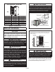
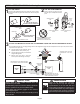
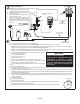
UNIT DIMENSIONS - INCHES (MM)
Model Number A B
ML17XP1-018-230 28-1/4 (718) 43-1/4 (1099)
ML17XP1-024-230 28-1/4 (718) 43-1/4 (1099)
ML17XP1-030-230 28-1/4 (718) 32-1/4 (819)
ML17XP1-036-230 32-1/4 (819) 32-1/4 (819)
ML17XP1-042-230 32-1/4 (819) 37-1/4 (946)
ML17XP1-048-230 32‐1/4 (819) 37-1/4 (946)
ML17XP1-060-230 32‐1/4 (819) 43-1/4 (1099)
FIGURE 1. Unit Dimensions
STEP 1 – SETTING THE UNIT
(Continued) – Unit Placement
NOTICE!
Roof Damage!
This system contains both refrigerant and oil. Some
rubber roong material may absorb oil, causing the
rubber to degrade. Failure to follow this notice could
result in damage to roof surface.
IMPORTANT
This unit must be matched with an indoor coil as specied
with AHRI. For AHRI Certied system match-ups and
expanded ratings, visit www.LennoxPros.com. Coils
previously charged with HCFC-22 must be ushed.
WARNING
To prevent personal injury, as well as damage to panels,
unit or structure, observe the following:
While installing or servicing this unit, carefully stow all
removed panels so that the panels will not cause injury
to personnel, objects or nearby structures. Also, take
care to store panels where they will not be subject to
damage (e.g., being bent or scratched).
While handling or stowing the panels, consider any
weather conditions (especially wind) that may cause
panels to be blown around and damaged.
IMPORTANT
The Clean Air Act of 1990 bans the intentional venting of
refrigerant (CFCs, HCFCs and HFCs) as of July 1, 1992.
Approved methods of recovery, recycling or reclaiming
must be followed. Fines and/or incarceration may be
levied for noncompliance.
IMPORTANT
Exhaust vents from dryers, water heaters and furnaces
should be directed away from the outdoor unit. Prolonged
exposure to exhaust gases and the chemicals contained
within them may cause condensation to form on the steel
cabinet and other metal components of the outdoor unit.
This will diminish unit performance and longevity
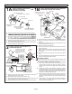
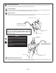
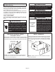
INSTALL UNIT AWAY
FROM WINDOWS
TWO 90º ELBOWS INSTALLED IN LINE SET
WILL REDUCE LINE SET VIBRATION
PLACEMENT
FIGURE 2
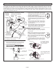
Install unit level or, if on a slope, maintain slope tolerance of 2
degrees (or 2 inches per 5 feet [50 mm per 1.5 m]) away from
building structure.
GROUND LEVEL
MOUNTING SLAB
BUILDING
STRUCTURE
DISCHARGE AIR
SLAB MOUNTING
FIGURE 3
IMPORTANT
This model is designed for use in check / expansion
valve systems only. An indoor expansion valve approved
for use with HFC-410A refrigerant must be ordered
separately and installed prior to operating the system.
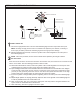
NOTE - An optional Unit Stand-O Kit (94J45) is available
for this unit. Black high-density polyethylene feet raise unit
o of mounting surface away from damaging moisture.
Four feet are furnished per order number.