
Phau Ntawv Qhia


Page 16
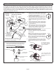
4 - Inspect the indoor coil drain pans and condensate
drains for rust, debris, obstructions, leaks or cracks.
Pour water in pans to conrm proper drainage from
the pan through to the outlet of the pipe. Clean or
replace as necessary.
5 - Inspect and clean indoor coil, if necessary.
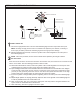
6 - Inspect the condition of the refrigerant lines and
conrm that pipes are not rubbing copper-to-
copper. Also, ensure that refrigerant pipes are not
being aected by indoor air contamination. Check
condition of insulation on the refrigerant lines.
Repair, correct, or replace as necessary.
7 - Inspect the duct system for leaks or other problems.
Repair or replace as necessary.
8 - Check for bearing/bushing wear on indoor blower
motor. Replace as necessary.
9 - If your heat pump is matched with a gas- or oil-red
furnace for auxiliary heating, indoor unit service
will also include inspection and cleaning of the
burners, and a full inspection of the gas valve, heat
exchanger and ue (exhaust) system.
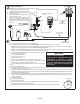
General System Test with System Operating
1 - Your technician should perform a general system
test. He will turn on the air conditioner to check
operating functions such as the startup and shuto
operation. He will also check for unusual noises or
odors, and measure indoor/outdoor temperatures
and system pressures as needed. He will check
the refrigerant charge per the charging sticker
information on the outdoor unit.
2 - Verify that system total static pressure and airow
settings are within specic operating parameters.
3 - Verify correct temperature drop across indoor coil.
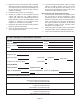
ML17XP1 Start-Up and Performance Checklist
Customer Address
Indoor Unit Model Serial
Outdoor Unit Model Serial
Notes:
START UP CHECKS
Refrigerant Type:
Rated Load Amps: Actual Amps Rated Volts
Actual Volts
Condenser Fan Full Load Amps Actual Amps:
COOLING MODE
Suction Pressure: Liquid Pressure:
Supply Air Temperature: Ambient Temperature: Return Air: Temperature:
System Refrigerant Charge (Refer to manufacturer's information on unit or installation instructions for required
subcooling and approach temperatures.)
Subcooling:
A — B = SUBCOOLING
Saturated Condensing Temperature (A)
minus Liquid Line Te mperature (B)
Approach:
A — B = APPROACH
Liquid Line Te mperature (A)
minus Outdoor Air Te mperature (B)
Indoor Coil Te mperature Drop (18 to 22°F)
A — B = COIL TEMP DROP
Return Air Te mperature (A)
minus Supply Air Temperature (B)