
Phau Ntawv Qhia


Page 14
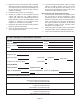
DEMAND DEFROST CONTROL (A108) DIAGNOSTIC LEDS
The state (O, On, Flashing) of two LEDs on the demand defrost control (DS1 [Red] and DS2 [Green]) indicate diagnostics
conditions that are described in table 3.
TABLE 3
DEMAND DEFROST CONTROL (A108) DIAGNOSTIC LEDS
DS1 and DS2 System Status, Fault and Lockout Codes
DS2
Green
DS1
Red
Type
Condition/Code Possible Cause(s) Solution
OFF OFF Status Power problem
No power (24V) to demand defrost
control terminals R and C or demand
defrost control failure.
1.
Check control transformer power (24V).
2.
If power is available to demand defrost control and
trol.
Simultaneous SLOW
Flash
Status Normal operation
Unit operating normally or in standby
mode.
None required.
Alternating SLOW
Flash
Status 5-minute anti-short cycle delay
Initial power up, safety trip, end of
room thermostat demand.
None required (jumper TEST pins to override)
Simultaneous FAST
Flash
Fault Ambient Sensor Problem
Sensor being detected open or shorted or out of temperature range. Demand defrost control
will revert to time/temperature defrost operation. (System will still heat or cool).
Alternating
FAST Flash
Fault Coil Sensor Problem
Sensor being detected open or shorted or out of temperature range. Demand defrost control
will not perform demand or time/temperature defrost operation. (System will still heat or cool.)
ON ON Fault Demand Defrost Control Failure
Indicates that demand defrost control has internal component failure. Cycle 24VAC power to
demand defrost control. If code does not clear, replace demand defrost control.
OFF
SLOW
Flash
Fault Low Pressure Fault
Restricted air flow over indoor or
outdoor coil.
Improper refrigerant charge in
system.
Improper metering device
installed or incorrect operation
of metering device.
Incorrect or improper sensor
location or connection to
system.
Remove any blockages or restrictions from coils
and/or fans. Check indoor and outdoor fan
motor for proper current draws.
Check system charge using subcooling
method.
Check system operating pressures and
compare to unit subcooling tables in this
instruction or located on unit access panel.
Make sure all pressure switches and sensors
have secure connections to system to prevent
refrigerant leaks or errors in pressure and
temperature measurements.
OFF ON Lockout
Low Pressure Lockout
SLOW
Flash
OFF Fault High Pressure Fault
ON OFF Lockout
High Pressure Lockout
(Each fault adds 1 strike to that code's counter; 5 strikes per code = LOCKOUT)
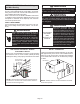
Homeowners Information
CAUTION
Before attempting to perform any service or maintenance,
turn the electrical power to unit OFF at disconnect switch.
In order to ensure peak performance, your system must
be properly maintained. Clogged lters and blocked air-
ow prevent your unit from operating at its most ecient
level. The system should be inspected and serviced be-
fore each cooling and heating season by a licensed pro-
fessional HVAC service technician (or equivalent).
Heat Pump Operation
Your new Lennox heat pump has several characteristics
that you should be aware of:
• Heat pumps satisfy heating demand by delivering large
amounts of warm air into the living space. This is quite
dierent from gas- or oil-red furnaces or an electric fur-
nace which deliver lower volumes of considerably hotter
air to heat the space.
• Do not be alarmed if you notice frost on the outdoor coil
in the winter months. Frost develops on the outdoor coil
during the heating cycle when temperatures are below
45ºF (7ºC). An electronic control activates a defrost cy-
cle lasting 5 to 15 minutes at preset intervals to clear the
outdoor coil of the frost.
• During the defrost cycle, you may notice steam rising
from the outdoor unit. This is a normal occurrence. The
thermostat may engage auxiliary heat during the defrost
cycle to satisfy a heating demand; however, the unit will
return to normal operation at the conclusion of the de-
frost cycle.
Homeowner Maintenance
The following maintenance may be performed by the
homeowner.
• Contact a licensed professional HVAC technician to
schedule inspection and maintenance appointments for
your equipment before each heating and cooling sea-
son.
• Check the indoor unit lter each month and replace the
lter, if necessary.
• Have your Lennox dealer show you where your indoor
unit lter is located. It will be either at the indoor unit
(installed internal or external to the cabinet) or behind
a return air grille in the wall or ceiling. Check the lter
monthly and clean or replace it as needed. Disposable
lters should be replaced with a lter of the same type
and size.