
Phau Ntawv Qhia


Page 13
Checking Refrigerant Charge
The ML17XP1 unit is factory-charged with enough HFC-
410A refrigerant to accommodate a 15-foot length of refrig-
erant piping. Charge should be checked and adjusted
using the tables provided on the charging procedure
sticker on the unit access panel. Detailed information
is given in the ML17XP1 Installation and Service Proce-
dures manual, which is available on LennoxPros.com.
Defrost System
This section addresses:
• Emergency Heat
• Defrost System Overview
• Defrost Control Connections, Jumper Settings and Fea-
tures
• Operational Mode Overview (Calibration, Normal and
Defrost)
• Defrost Cycle Actuation
EMERGENCY HEAT (AMBER LIGHT)
An emergency heat function is designed into some room
thermostats. This feature is applicable when isolation of
the outdoor unit is required, or when auxiliary electric heat
is staged by outdoor thermostats. When the room thermo-
stat is placed in the emergency heat position, the outdoor
unit control circuit is isolated from power and eld-provid-
ed relays bypass the outdoor thermostats. An amber indi-
cating light simultaneously comes on to remind the home-
owner that he is operating in the emergency heat mode.
Emergency heat is usually used during an outdoor unit
shutdown, but it should also be used following a power
outage if power has been o for over an hour and the out-
door temperature is below 50°F (10°C). System should be
left in the emergency heat mode at least six hours to allow
the crankcase heater sucient time to prevent compres-
sor slugging.
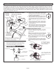
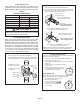
DEFROST SYSTEM OVERVIEW
The control monitors ambient temperature, outdoor coil
temperature, and total run time to determine when a de-
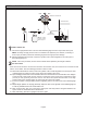
frost cycle is required. The coil temperature probe is de-
signed with a spring clip to allow mounting to the outside
coil tubing. The location of the coil sensor is important for
proper defrost operation.
NOTE – The demand defrost control accurately measures
the performance of the system as frost accumulates on the
outdoor coil. This typically will translate into longer running
time between defrost cycles as more frost accumulates on
the outdoor coil before the demand defrost control initiates
defrost cycles.
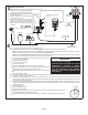
DEFROST CONTROL CONNECTIONS, JUMPER SET-
TINGS AND FEATURES
Defrost Temperature Termination Jumper Settings
(P1)
The demand defrost control selections are: 50, 70, 90 and
100°F (10, 21, 32 and 38°C). The shunt termination pin
is factory set at 50°F (10°C). If temperature shunt is not
installed, default termination temperature is 90°F (32°C).
Test Pins (P1) Function
Placing the jumper on the eld test pins (P1) allows the
technician to:
• Clear short cycle lockout
• Clear ve-strike fault lockout
• Cycle the unit in and out of defrost mode
• Place the unit in defrost mode to clear the coil
Compressor Delay Mode (P5)
The demand defrost control has a eld-selectable function
to reduce occasional sounds that may occur while the unit
is cycling in and out of the defrost mode. When a jumper
is installed on the DELAY pins, the compressor will be
cycled o for 30 seconds going in and out of the defrost
mode. Units are shipped with jumper installed on DELAY
pins.
NOTE – The 30 second o cycle is NOT functional when
jumpering the TEST pins.
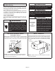
HIGH PRESSURE SWITCH (S4)
This unit is equipped with a high pressure switch which is
located on the liquid line. The SPST, normally closed pres-
sure switch opens when liquid line pressure rises above
the factory setting of 590 + 15 psig and automatically re-
sets at 418 + 15 psig.
LOW PRESSURE SWITCH (S87)
This unit is equipped with a low pressure switch which
is located on the suction line. The SPST, normally open
pres sure switch opens when suction line pressure falls
below the factory setting of 25 ± 5 psig and closes when
pressure rises at 40 ± 5 psig.